Most of the time, circuit breakers just do their job quietly. You flip a switch, and the lights turn on. No sparks, no drama. But inside those breakers, tiny gaps between wires can sometimes create a hidden risk—one that’s easy to overlook.
That’s where interphase barriers come in. These small, simple pieces of plastic sit between the wires and quietly do their job, keeping electricity where it belongs. You probably see them in the panel, but most people have no idea what they actually do—they stop sparks from jumping between wires and causing damage.
Even in busy, messy panels, interphase barriers help keep things safe. They don’t make noise or draw attention, but their presence can make the difference between a system that runs smoothly and one that suddenly causes trouble. Sometimes, the smallest parts do the most important work.
What Are Interphase Barriers?
Interphase barriers are insulation accessories most commonly used with MCCBs, though similar designs appear in other electrical equipment as well. You can think of them as protective walls that sit between the three phases of a system, keeping electricity safely separated. They’re usually made from high-grade insulating plastic that can handle high temperatures and electrical stress.

The Basic Design
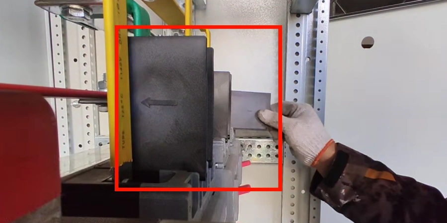
These barriers clip onto the front of MCCBs without requiring any tools. Most manufacturers design them to fit specific breaker frame sizes, so you’ll need to match the barrier model to your circuit breaker. For a standard 3-pole breaker, you typically need two barriers. For 4-pole configurations, you’ll need three.
The installation is straightforward. The barriers slide into position between the phase terminals and lock into place using mounting clips. At Sincede, we produce our mccbs with high-precision casing molds, ensuring these barriers slide in perfectly without the "wobble" that can lead to safety gaps. They create a physical separation that extends from the terminal area down past the arc chutes inside the breaker. The placement isn’t random—it’s carefully engineered to provide maximum protection right where phase-to-phase contact is most likely to occur.
What They Actually Do?
The main job of an interphase barrier is preventing electrical arcs from jumping between adjacent phases. In a three-phase system, each phase carries current at different voltage potentials—they’re typically 120 degrees out of phase with each other. When phases get too close, or when conductive material bridges the gap between them, you get a phase-to-phase fault. That’s when things go very wrong, very fast.
Interphase barriers create protected zones between phases. They don’t just block direct contact—they also contain arc motion if a fault does occur. Research shows that these barriers prevent downward arc movement and create a stabilizing effect on electrical arcs. Instead of an arc wandering unpredictably and potentially damaging other equipment, the barriers help direct the arc energy in a more controlled manner.
Phase-to-Phase Arc Faults and Safety Risks
I’ll be honest—the first time I saw a video of an arc flash test, I couldn’t believe what I was watching. The temperature, the light, the sheer violence of it. That’s when I understood why electrical safety professionals take this stuff so seriously.
Phase-to-phase arc faults are one of the most dangerous problems in power systems. They usually happen when two phase wires accidentally short circuit. When an arc like this forms, temperatures can reach 35,000°F (19,400°C)—about four times hotter than the surface of the sun. Take a moment to picture that.
How These Faults Happen?
Phase conductors can get dangerously close for several reasons. Even brand-new equipment may have tighter-than-ideal spacing due to manufacturing tolerances. Over time, normal heating and cooling cycles cause thermal expansion, which can slightly shift conductors. Vibration from nearby machinery can also move things around. Add in some conductive dust or debris—which you’ll find in plenty of industrial environments—and you’ve created a perfect storm.
When maintenance work happens, human error becomes another factor. A dropped tool, a loose connection, or improper installation can all create a path for phase-to-phase contact. Field technicians often find wire scraps, metal shavings, or even small tools that lodged iside panels from years past.
One detail that often surprises people: the ionized gas that MCCBs release during short-circuit breaking operations is highly conductive. When a breaker interrupts a fault, it vents this ionized gas through exhaust ports. If adjacent bare live parts are too close, that gas can bridge the gap and create an unintended phase-to-phase short circuit—right when the system is already under stress.
The Cascade of Problems
When phase-to-phase contact occurs, extremely high currents flow between the phases. We’re not talking about normal operating currents—we’re talking about fault currents that can be tens of thousands of amperes. The arc that forms releases its energy in multiple dangerous forms:
The thermal energy causes severe burns to anyone nearby. The pressure wave can rupture eardrums and throw workers across the room. The intense light can cause temporary or permanent vision damage. Equipment gets destroyed—not just at the fault location, but potentially cascading through connected systems. Production stops. Costs mount quickly.
According to industry data, the average direct cost of an electric shock injury is $86,528 per incident. When you factor in indirect costs—lost production time, equipment replacement, investigations, increased insurance premiums—the total average cost jumps to $181,708 per incident. And that’s just the financial side. The human cost of serious injuries or fatalities can’t be measured in dollars.
Risk Factors That Increase Exposure
Several factors determine how severe an arc flash incident can be. Higher available fault currents create larger, more intense arcs. Longer arc duration releases more energy—which is why fast-acting protection is so valuable. The distance from the arc source matters tremendously; workers closer to the fault face exponentially higher exposure risk.
The voltage rating of the system plays a role too. Higher voltages mean greater potential for arc formation and more energy released when arcs occur. This is why regulatory requirements get stricter as voltage levels increase.
| Arc Flash Hazard | Impact | Typical Value |
|---|---|---|
| Temperature | Severe burns, equipment damage | 35,000°F (19,400°C) |
| Incident Energy | Determines PPE requirements | 3-20+ cal/cm² |
| Pressure Wave | Hearing damage, physical trauma | 140+ decibels |
| Light Radiation | Eye damage, blindness risk | UV and IR exceeding safe limits |
When Do You Need Interphase Barriers?
This is where things get practical. Many people ask about when we need to install the interphase barriers. The answer isn’t always straightforward, but let me break it down based on what I’ve learned from working with engineers and reviewing installation standards.
Mandatory Installation Scenarios
For circuit breakers operating at voltages of 500V or higher, interphase barriers are mandatory. This isn’t a suggestion—it’s a requirement based on industry standards. At these voltage levels, the arc flash risk increases dramatically. The thermal energy and incident energy calculations exceed safe thresholds without proper phase separation.
There’s also a spacing rule you need to know: if the insulation distance between phases is 14mm or less, installing interphase barriers is strongly advised. This 14mm threshold comes from IEC 60947-2 and represents the minimum air gap required to prevent arcing under standard conditions. Many MCCBs, especially compact designs, have natural phase spacing that falls below this threshold. In those cases, barriers aren’t optional—they’re necessary to meet minimum safety clearances.
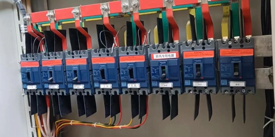
When multiple MCCBs are installed side-by-side with zero distance between consecutive units, manufacturers like Schneider Electric recommend installing interphase barriers or terminal shields to ensure proper insulation of live parts. This is especially important in dense panel configurations where space is tight.
When Barriers Are Strongly Recommended?
For MCCBs operating below 500V, interphase barriers typically fall into the "recommended" category rather than mandatory. But here’s an interesting observation from my time in the industry: many manufacturers now include interphase barriers as standard accessories with their circuit breakers.
At Sincede, this is how we do business. We don’t treat safety as an expensive extra. We include two interphase barriers in every box for free—this is exactly enough for a standard 3-pole breaker. We believe basic safety shouldn’t have hidden fees. After all, preventing an accident is far cheaper than paying for the damage of one.
Why would they do this if barriers aren’t required? Because the cost of prevention is significantly less than the cost of a single arc flash incident. When you’re looking at potential costs exceeding $180,000 per incident, spending a few dollars on barriers during initial installation is an obvious choice.
Circuits handling high fault currents—anything above 50kA—benefit greatly from barrier installation even if not strictly required by code. The larger fault currents create more intense and larger arc flashes, so the protective value of barriers increases proportionally.
Environmental and Operational Considerations
Industrial environments with pollution degree 3 or higher should seriously consider barrier installation regardless of voltage level. These are places with conductive dust, moisture, or corrosive atmospheres. In these conditions, the risk of phase-to-phase contact increases because contamination can create conductive paths between phases.
Facilities operating under heightened safety requirements—union electrical codes, insurance policies, or corporate safety standards that exceed minimum regulatory requirements—often mandate barrier installation across the board.
| Scenario | Requirement Level | Key Threshold |
|---|---|---|
| Voltage ≥500V | Mandatory | Per IEC standards |
| Phase spacing ≤14mm | Strongly advised | Minimum clearance requirement |
| Side-by-side MCCBs (zero spacing) | Recommended | Best practice per manufacturers |
| High fault currents (>50kA) | Recommended | Increases arc intensity |
| Harsh environments (pollution degree 3+) | Recommended | Conductive contamination risk |
Key Benefits: Enhanced Safety and Arc Flash Protection
Interphase barriers play an important role in keeping electrical systems safe. They help control how electrical arcs form, reduce the amount of energy released during a fault, and limit how far the damage spreads. When installed correctly, these simple parts can be the difference between a small, contained issue and a major arc flash event.
Arc Containment and Energy Reduction
Insulating barriers can stabilize arc behavior and reduce arc voltage by approximately 26% through their stabilizing effect on arc lengths. I know that sounds surprising—how does adding a barrier reduce voltage? The answer is in physical containment: barriers prevents chaotic arc from wandering unpredictably, which otherwise creates erratic high-energy discharge.
The real impact shows up in incident energy reduction. In comprehensive testing of internal arc-rated switchgear systems incorporating barrier technology, In tested configurations, incident energy has been reduced by over 8 times—dropping from dangerously high levels down to approximately 3.0 cal/cm² at 18 inches. Actual results depend on system voltage, available fault current, and protective device clearing time.
Think about what that means practically. Without barriers, you might need workers wearing heavy arc-rated suits with face shields, which are hot, uncomfortable, and restrict movement. With barriers reducing incident energy to 3.0 cal/cm², you’re potentially looking at Category 2 PPE instead of Category 4. That’s the difference between working in regular protective clothing versus looking like you’re ready to walk into a blast furnace.
Pressure Relief and Directional Control
Interphase barriers work together with other arc containment features to guide arc energy away from sensitive areas. Pressure relief vents and arc chutes, enhanced by the presence of barriers, ensure that electrical systems can remain operational after an arc fault incident. They contain the arc flash damage to a limited zone instead of letting it propagate through the entire electrical distribution system.
After arc flash incidents, panels with interphase barriers typically show localized damage—such as charring around the fault point or limited melting of nearby components. In contrast, panels without barriers often suffer much wider damage, with adjacent breakers and busbars destroyed, sometimes requiring full panel replacement instead of a targeted repair.
Compliance and Insurance Benefits
Equipment with interphase barriers demonstrates compliance with critical arc flash protection standards including NFPA 70E and IEEE 1584. Installing barriers is one of the simplest ways to show you’re mitigating arc flash risks.
From a business perspective, compliance reduces penalties during inspections. But there’s another often-overlooked benefit: lower insurance premiums. When you can demonstrate reduced risk through documented safety improvements like barrier installation, insurance carriers often recognize that with better rates. The barriers essentially pay for themselves through reduced insurance costs over time.
Long-Term Reliability
Here’s something that doesn’t get talked about enough: barriers protect your equipment investment. When a fault occurs in a properly protected system, the damage stays localized. You might need to replace one breaker instead of an entire panel. Production downtime measures in hours instead of days or weeks. The cost difference is enormous.
| Benefit Category | Without Barriers | With Barriers |
|---|---|---|
| Incident Energy (at 18") | 10-20+ cal/cm² | 3.0 cal/cm² |
| PPE Requirement | Category 4 (heavy suit) | Category 2 (lighter protection) |
| Damage Spread | Multi-panel cascade | Localized to fault area |
| Average Incident Cost | $181,708 | Significantly reduced |
| Equipment Downtime | Days to weeks | Hours to days |
Conclusion
Every arc flash prevented is a reminder that the cost of inaction far outweighs the investment in protection. Interphase barriers may be small pieces of plastic, but they reflect a principle that applies everywhere: thoughtful preparation often prevents the biggest consequences.