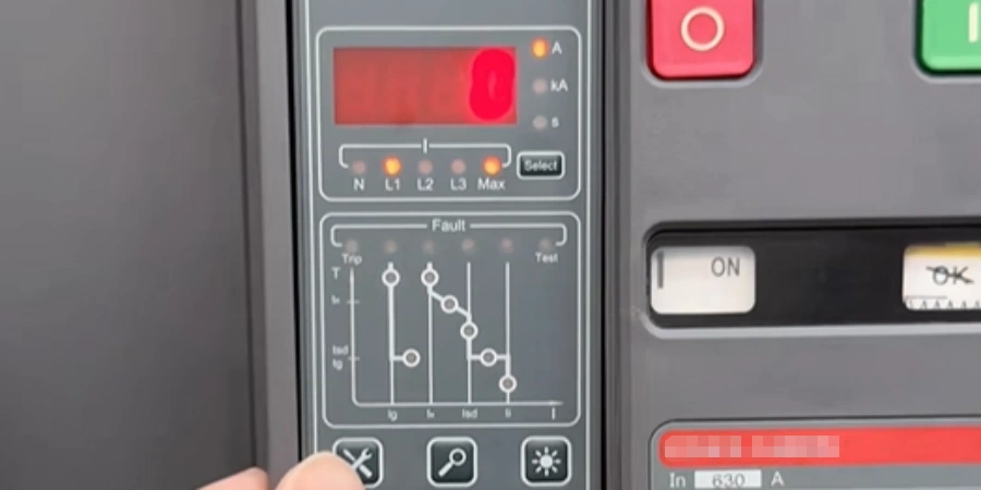
When we talk about ACBs or smart MCCBs, you’ll often hear the term LSIG. Many people just see it as a set of letters, but it actually refers to a group of protection features that keep both equipment and people safe.
These features show up more in ACBs than MCCBs because ACBs have to handle big currents and more complex power setups. When we set up main breakers, we carefully adjust LSIG to prevent unnecessary trips while making sure the system reacts fast when a real fault happens.
Knowing how these features work makes systems more reliable and gives engineers confidence when designing or maintaining them. They act like an invisible safety net, quietly protecting the entire distribution system from trouble.
What LSIG Stands For?
LSIG represents 4 distinct protection functions that work together to safeguard your electrical distribution system:
-
L (Long-time) handles overload protection, guarding against slow, sustained overcurrents—like equipment drawing slightly more than it should over long periods.
-
S (Short-time) provides delayed short-circuit protection, giving downstream breakers the chance to clear faults first.
-
I (Instantaneous) offers immediate protection against severe short-circuits that require fast interruption.
-
G (Ground-fault) detects faults that don’t register as phase overcurrents but can still cause serious fire or shock hazards.
These functions work together as a layered defense. Long-time protection addresses thermal stress, short-time protection ensures selective coordination, instantaneous protection handles extreme short circuits, and ground-fault protection safeguards personnel and property. Understanding how each function operates is essential to designing a safe and reliable electrical distribution system.
Breaking Down Each Protection Function
Now that we know what LSIG stands for, let’s look at each protection function in detail.
L – Long-time (Overload) Protection
The L function is your first line of defense against thermal damage. It monitors current continuously and trips the breaker when the load exceeds a set threshold for longer than the programmed delay. Think of it as a thermal guardian that knows your cables and equipment can handle brief overloads during motor starting or transformer energization, but will protect against sustained overcurrent that causes heat buildup.
In our production facility, we test the long-time function by injecting a steady current—say, six times the pickup setting (6 × Ir)—and verifying that the breaker trips within the specified time band. The pickup setting, typically labeled Ir, can be adjusted from about 0.4 to 1.0 times the breaker’s rated current (In). For a 1600 A breaker, you might set Ir to 0.9 × In (1440 A), meaning the protection activates when load current exceeds 1440 A.
The time delay follows an inverse-time characteristic—higher overcurrents trip faster. At 1.2 × Ir, the breaker might wait several minutes before tripping. At 6 × Ir, it could trip in 8 to 12 seconds, depending on your settings. This curve mimics the thermal behavior of cables, which can tolerate short-duration overloads but suffer damage from prolonged heating. Modern electronic trip units often include thermal memory, meaning if the breaker experiences an overload that doesn’t trip it, the trip unit remembers that heating and adjusts the next trip time accordingly.
One thing I’ve learned is that incorrect long-time settings cause more nuisance trips than any other function. If you set Ir too close to the normal load current—say, at 0.8 × In when your typical load runs at 75% of breaker rating—you’ll get trips during normal operation when multiple motors start or HVAC systems kick on. On the other hand, setting Ir too high defeats the purpose of overload protection. Your cables might be rated for 1200 A continuous, but if you set a 1600 A breaker’s Ir to 1.0 × In (1600 A), you’ve created a gap where the cable can overheat without the breaker responding in time.
S – Short-time (Short-Circuit with Delay) Protection
Short-time protection handles fault currents that are too high to be normal operation but low enough that they might be on a downstream circuit. The key word here is "selectivity"—making sure the right breaker trips for a given fault. The S function introduces an intentional delay, giving downstream breakers time to clear faults in their zones before the upstream breaker intervenes.
Here’s what many people don’t realize—short-time protection isn’t just about the delay. It’s also about the pickup setting (Isd). Typical short-time pickup ranges from 2 to 10 times In, though this varies by manufacturer. For a 1600 A breaker, you might set Isd to 6 × In (9600 A). This means any fault current above 9600 A enters the short-time protection zone. If the fault current is, say, 8000 A—above Ir but below Isd—the long-time function would eventually trip, but it might take too long. That’s where good coordination studies come in; they ensure there are no gaps in coverage.
Another aspect of S-function protection is the choice between I²t ON and I²t OFF modes. With I²t ON, the trip time follows an inverse curve based on the square of the current—higher fault currents trip faster within the short-time band. This helps with coordination and limits the energy let-through during faults. With I²t OFF, the delay is constant regardless of current magnitude within the S-band. Some projects specify I²t ON for better selectivity and reduced arc-flash incident energy, while others use I²t OFF for simpler, more predictable timing.
I – Instantaneous Protection
When fault currents reach levels that could cause immediate damage—typically 10 to 15 times the breaker rating—you need instantaneous protection. There’s no time for coordination, no deliberate delay. The breaker needs to open its contacts within a cycle or two to limit the mechanical stresses and thermal effects.
I remember watching a short-circuit test at a testing laboratory where they demonstrated the difference between a breaker with proper instantaneous settings and one with the I-function set too high. In the first test, the breaker opened so quickly that the fault energy was minimal. In the second test, with the I-function disabled, the arcing continued for several cycles longer, and you could see the visible damage to the test busbars afterward.
The instantaneous pickup setting (Ii) is typically adjustable from 2 to 15 times In, though 10 to 12 times In is common for main breakers. The challenge is setting it high enough to avoid tripping on inrush currents—transformers can pull 8 to 12 times their rated current for a few cycles during energization, and motors have similar starting behaviors—but low enough to provide meaningful protection against severe faults.
During factory testing, we verify instantaneous trip times using a high-current pulse. For a breaker rated at 1600 A with Ii set to 12 × In (19,200 A), we’d inject a current pulse of, say, 25 kA and measure how quickly the breaker opens. The trip time should be less than one cycle (about 16.7 milliseconds at 60 Hz). This fast response limits arc-flash hazard levels and reduces the stress on busbars and connected equipment.
G – Ground-fault Protection
Ground-fault protection is the function that often gets overlooked, yet it’s critical for safety and fire prevention. Unlike phase overcurrent protection, which detects imbalances between phase currents, ground-fault protection looks for current flowing to ground that shouldn’t be there.
The G function typically uses residual current sensing—it adds up all the phase currents and the neutral current (if applicable), and any difference represents current flowing through an unintended path to ground. In a balanced system with no ground-fault, the sum of phase currents equals the return current. When there’s a ground-fault, you get an imbalance.
I’ve reviewed incident reports where ground-faults caused fires because the phase overcurrent protection didn’t respond quickly enough. A fault drawing 400 amperes to ground might not be enough to trip a 1600 A breaker’s long-time function quickly, especially if it’s set to protect against overloads rather than low-level faults. But 400 amperes arcing through a loose connection or damaged insulation generates tremendous heat in a localized area. That’s where the G function saves the day.
Ground-fault pickup settings (Ig) are typically much lower than phase overcurrent settings—often in the range of 0.2 to 0.6 × In, or sometimes expressed as a fixed ampere value like 200 to 800 A. For our 1600 A example breaker, you might set Ig to 0.3 × In (480 A). The time delay (Tg) is usually short—0.1 to 0.4 seconds—to quickly isolate ground-faults while still allowing coordination with downstream ground-fault protection.
Ground-fault protection is often required by code for larger services. IEC 60364 and many national codes mandate ground-fault protection on main disconnects above certain ampacity, particularly in commercial and industrial installations. Even when it’s not strictly required, specifying LSIG at the main panel is considered best practice for safety and property protection.
Conclusion
Good protection isn’t visible when everything runs smoothly—but it’s critical when things go wrong. LSIG functions provide that quiet safety net, preventing small faults from turning into serious problems. Understanding and applying them wisely ensures systems stay reliable, efficient, and safe for everyone around them.