When I first started working in the electrical industry, I was quickly introduced to the world of circuit breaker specifications.
At the time, I was confused by all the acronyms—Icu, Ics, Icw, Icm—felt like an alphabet soup. I could barely keep track of what each term meant, let alone how they impacted the safety of the systems I was working on.
As I dug deeper into the topic, I started to see how these seemingly small numbers actually play a huge role in ensuring the safety and reliability of electrical systems.
In one of our previous blogs(Icu and Ics on Circuit Breakers: What You Need to Know), we discussed ICU and ICS ratings and how they relate to a circuit breaker’s interrupting capacity. This time, let’s take a closer look at ICW and ICM ratings—two crucial but often overlooked specifications that are just as important in keeping systems running smoothly.
What Are ICW and ICM Ratings?
Terms like ICU and ICS were easy to grasp, but ICW and ICM were a bit more confusing. As I began to look deeper into these ratings, I realized they were critical to understanding how breakers handle fault conditions. They often don’t get the attention they deserve, especially from those of us outside the engineering world.
Let’s keep it simple. ICW stands for Rated Short-Time Withstand Current, and ICM means Rated Short-Circuit Making Capacity. You can think of ICW as a breaker’s ability to “hold steady” during a fault, and ICM as its ability to “snap shut” even when a fault is already happening. Together, they determine whether your system stays intact when faults occur.
The Real-World Impact of These Ratings
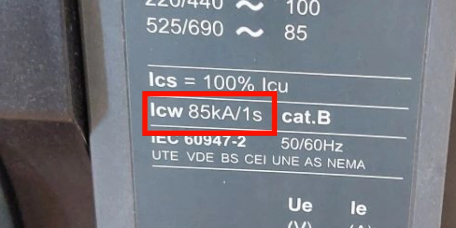
ICW is about endurance. It tells you how much short-circuit current a closed breaker can handle for a set amount of time—usually between 0.05 and 1 second—without damage. This isn’t about interrupting the fault, but about surviving it. You’ll see values expressed in kiloamperes (kA) RMS, with typical test durations of 0.1s, 0.25s, 0.5s, or 1s depending on the system design.
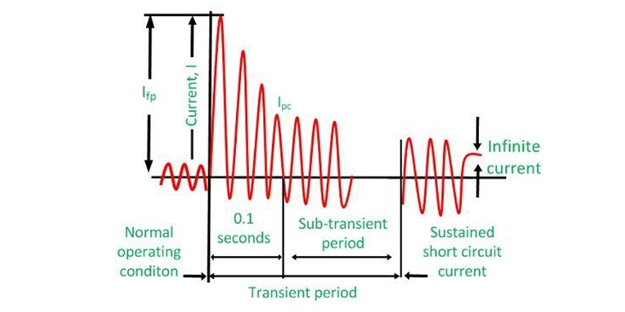
ICM, on the other hand, is about what happens when a breaker closes while a fault is already present. Imagine a breaker being switched on at the exact moment the system has a short circuit. In that instant, the current doesn’t just flow—it surges to a very high peak, much higher than the normal fault current.
This might sound unusual, but it happens in real systems. For example, when someone quickly restores power without realizing a fault is still there, or when an automatic transfer switch reconnects during a fault. ICM tells us whether the breaker can survive that sudden surge without breaking apart.
Why Standard Ratings Aren’t Enough?
Here’s where it gets tricky. A breaker’s ultimate breaking capacity (ICU) doesn’t tell the full story. You might buy a breaker labeled “50 kA ICU,” but its ICW could only be 30 kA for 1 second. That gap matters a lot when you’re designing coordinated protection schemes.
According to IEC 60947-2 standards, the relationship between these ratings follows certain patterns. For molded case circuit breakers (MCCBs), ICW is usually only 40–50% of ICU. Air circuit breakers (ACBs) do better, with ICW values around 60–67% of ICU.
Understanding the Testing Context
Both ICW and ICM ratings come from real-world stress tests.
-
ICW testing keeps the breaker closed while fault current flows for the rated time. The breaker must hold up thermally and mechanically without tripping. In other words, it proves the breaker can “ride out the storm” until upstream protection clears the fault.
-
ICM testing is more dramatic. The breaker is forced to close onto an existing fault, and the test measures the peak current in the first half-cycle. Because of asymmetry and system inductance, this peak can reach 1.7–2.2 times the RMS fault current. The test ensures the breaker’s mechanism doesn’t buckle under the sudden electromagnetic forces.
Key Differences Between ICW and ICM
Many people are still confused about ICW and ICM, or don’t fully understand how they differ. Let me break it down and share the key distinctions between these two important ratings.
The fundamental difference lies in timing and purpose. ICW is all about endurance—how long your breaker can withstand fault current without failing up. ICM, on the other hand, focuses on the moment of maximum stress—the instant when a breaker closes onto an existing fault.
Current Types and Measurement Methods
ICW deals with RMS (Root Mean Square) current values sustained over time. When we say a breaker has an ICW of 30 kA for 1 second, we’re talking about continuous thermal and electromagnetic stress. The breaker must maintain its structural integrity, keep its contacts properly closed, and avoid any damage that would prevent normal operation afterward.
ICM is all about the instantaneous peak current—the highest current spike that occurs during the first half-cycle when the breaker closes onto a fault. This peak can be 1.7 to 2.2 times the RMS fault current, depending on factors like power factor and system impedance.
Operational Scenarios and Applications
Over the years, understanding when each rating matters has helped me make better specification decisions.
-
ICW becomes crucial in selective coordination schemes, where upstream breakers must stay closed while downstream devices clear faults. Imagine a manufacturing facility where the main feeder is critical to the whole operation. The upstream breaker must be able to withstand downstream faults without tripping, to avoid shutting down the entire production line.
-
ICM ratings are essential during scenarios like restoration activities, automatic transfer operations, or when breakers are manually closed onto faulted circuits. For instance, in a hospital, emergency transfer switches might need to close onto partially faulted circuits, so knowing the ICM rating ensures reliable operation when power restoration is urgent.
Time Duration Considerations
| Rating Type | Time Frame | Current Type | Primary Stress |
|---|---|---|---|
| ICW | 0.05s to 1s | RMS | Thermal/Electromagnetic |
| ICM | Single half-cycle (~0.01s) | Peak instantaneous | Mechanical forces |
The time difference between ICW and ICM is key. ICW events last long enough to generate significant heat and sustained electromagnetic stress, which can damage components.
In contrast, ICM events are very brief but generate massive mechanical forces that can physically deform or break breaker components if the rating is exceeded.
Protection Philosophy Impact
From a protection coordination standpoint, ICW allows for time-selective schemes where fault clearing follows a pre-defined order. Higher-rated breakers upstream can wait for lower-rated breakers downstream to clear faults first, ensuring that power remains available to the rest of the system.
ICM ratings, on the other hand, support operational flexibility. They ensure that breakers can safely close onto faulted circuits when necessary, especially in emergency situations where the priority is restoring power quickly, even if it means dealing with existing faults.
Calculating ICM from ICU Values
The relationship between ICM and ICU follows a predictable pattern that depends on the system’s power factor. The formula is straightforward:
ICM = k × ICU
Where k is a multiplication factor determined by the short-circuit power factor (cos φ) of your system.
Understanding the K-Factor
The k-factor reflects how much the peak fault current exceeds the RMS value during asymmetrical fault conditions. In systems with higher inductance (lower power factor), this asymmetry increases, resulting in higher peak currents during the first half-cycle.
| ICU Range (kA) | Power Factor (cos φ) | k-Factor | ICM Calculation |
|---|---|---|---|
| 6-10 | 0.5 | 1.7 | 1.7 × ICU |
| 10-20 | 0.3 | 2.0 | 2.0 × ICU |
| 20-50 | 0.25 | 2.1 | 2.1 × ICU |
| >50 | 0.2 | 2.2 | 2.2 × ICU |
Real-World Calculation Examples
Let’s walk through a couple of real-world examples:
For a data center with a 65 kA ICU breaker in a system where cos φ = 0.25, the ICM calculation is:
ICM = 2.1 × 65 = 136.5 kA peak
This matches typical manufacturer specs for high-performance air circuit breakers.
In an industrial application with 25 kA ICU molded case breakers and cos φ = 0.3, the ICM is:
ICM = 2.0 × 25 = 50 kA peak
This explains why many industrial MCCB specifications show ICM values around 42.5-50 kA for 25 kA ICU ratings.
While these calculations help in design, the reliability of the breaker ultimately depends on the manufacturing quality. To ensure the device actually performs to these specifications during a fault, precise control over production is essential.
System Power Factor Considerations
When calculating ICM, it’s essential to know your system’s power factor during fault conditions. Power factor varies based on load characteristics and fault impedance.
-
Motor-heavy industrial systems typically operate with a power factor between 0.2 and 0.3 during faults.
-
Commercial buildings with mixed loads often see values between 0.3 and 0.5.
The power factor during faults is usually much lower than normal operating conditions, because fault impedance often includes mainly inductive components (like cables, transformers, and motor reactances), while resistive loads are often bypassed or overwhelmed by the fault current.
Practical Application Guidelines
When selecting breakers, ensure that the calculated ICM meets or exceeds the prospective peak fault current at the installation point. This means factoring in not only the current values but also any future system expansions that could increase fault levels.
For critical applications, choose breakers with ICM ratings at least 20% above the calculated requirement. This margin accounts for potential system changes, measurement uncertainties, and aging effects. It’s saved me from specification issues in projects where fault studies were updated after equipment selection.
Understanding these calculations allows you to make quick, informed decisions, especially during design reviews where time pressures can lead to over-specifying or, worse, insufficient protection.
Why These Ratings Matter in Selective Coordination?
When it comes to electrical protection, the importance of ICW and ICM ratings often becomes clear when a coordination failure occurs. In these situations, critical systems like production lines, hospitals, or data centers can experience unexpected downtime, simply because the right ratings weren’t properly considered when selecting breakers.
Selective coordination is key to maintaining system reliability. It ensures that only the breaker closest to the fault trips, allowing the rest of the system to continue running. ICW ratings play a crucial role in this process, as they determine whether upstream breakers can withstand fault currents long enough for downstream devices to clear the fault first.
Time-Current Coordination Fundamentals
In a well-coordinated system, each protection device has a specific time delay before it operates. When a fault occurs, the device closest to the fault should trip first—typically within 0.1 to 0.5 seconds. Upstream devices need to stay stable during this period, which is where ICW comes into play.
Take a typical industrial distribution system: you’ve got a main breaker feeding multiple motor control centers (MCCs). When a fault occurs in one MCC, the feeder breaker should trip within 0.1 seconds. However, the main breaker must hold steady and withstand the fault current during this time without tripping. If the ICW rating of the main breaker isn’t enough, it may trip along with the feeder breaker, causing the entire facility to shut down unnecessarily.
Real-World Coordination Challenges
The coordination interval—the time gap between upstream and downstream devices operating—determines the required ICW rating. In systems with tight coordination requirements, this interval could be as short as 0.1 seconds. For critical facilities like hospitals or manufacturing plants, intervals of 0.5 to 1.0 seconds are more common to ensure reliable operation.
Through years of protection coordination studies, it has been observed that limitations in ICW ratings often compel designers to accept longer coordination intervals than ideally required. This can result in slower fault clearing times and increase unnecessary stress on equipment.
Emergency and Restoration Operations
ICM ratings are essential during emergency situations when power needs to be restored quickly. Emergency procedures often involve closing breakers onto circuits that may still have fault conditions or be in an unstable state.
A prime example of this is in hospital emergency systems. During power outages, automatic transfer switches need to close emergency generators onto loads that might include partially faulted circuits. The ICM rating of these transfer switches determines whether they can safely energize the emergency loads or fail during the process.
Economic Impact of Proper Coordination
| Facility Type | Coordination Failure Cost | Critical ICW Duration |
|---|---|---|
| Manufacturing Plant | $10,000-50,000/hour | 0.5-1.0 seconds |
| Data Center | $5,000-15,000/minute | 0.1-0.5 seconds |
| Hospital | Safety Critical | 1.0 seconds minimum |
The economic impact of coordination failures goes beyond immediate production losses. Equipment damage from prolonged fault exposure, restart costs, and even safety incidents all contribute to the total cost of poor protection coordination.
While proper ICW and ICM specifications may increase the upfront cost of individual breakers by 10-20%, this investment pays off by preventing costly facility-wide outages and protecting expensive downstream equipment from extended fault exposure.
Conclusion
Understanding ICW and ICM ratings is crucial for designing reliable electrical protection systems. These ratings help ensure that breakers can handle fault conditions without failing, preventing costly system outages.
By considering both endurance and short-circuit making capacity, engineers can enhance system stability and safety.