Modern electrical systems are more complicated than ever. With sensitive electronics, high-power motors, and variable loads, a single-stage breaker often isn’t enough. Small faults can quickly become serious problems, causing equipment damage, downtime, or even safety risks.
Three-stage protection, also called LSI (Long-time, Short-time, Instantaneous), acts like a layered safety system. Each stage responds to different types of faults: slow overloads, moderate short circuits, and sudden, dangerous spikes. By reacting at the right speed and in the right way, these layers protect equipment while keeping the system running smoothly.
When all three stages work together, the system can handle minor issues without interruption, stop moderate faults before they spread, and react instantly to dangerous problems. It’s a smarter, more reliable way to keep electricity under control and ensure both safety and uptime.
What Is Three-Stage Protection?
At first glance, the three-stage protection system can feel like just another layer of technical jargon. In fact, it’s the foundation of electrical safety—and it’s what keeps systems running smoothly while avoiding costly downtime.
Think of it as your electrical system’s immune response. Just like your body fights off different types of threats in different ways, some types of molded case circuit breakers (MCCBs) use three layers of protection. Each layer—Long-time (L), Short-time (S), and Instantaneous (I)—is designed for a specific type of fault. Together, they respond with the right speed and intensity to keep equipment safe and reliable.
The LSI Framework: A Coordinated Defense
What makes three-stage protection powerful isn’t just the three layers themselves, but how they work together. Instead of one trip mechanism reacting the same way to every fault, the LSI framework acts with what I like to call “selective response.”
-
Long-time protection covers overloads that, if ignored, would slowly damage equipment.
-
Short-time protection handles moderate faults, while still giving downstream devices a chance to clear the problem first.
-
Instantaneous protection reacts immediately when a dangerous short circuit threatens safety or equipment.
This coordination is crucial in real-world systems. With a three-stage setup, downstream breakers handle faults first, preventing upstream devices from shutting off unnecessarily. This ensures smoother operation, fewer disruptions, and a higher level of safety and reliability.
Why One Stage Isn’t Enough Anymore?
You might wonder: if older breakers worked with only one protection stage, why complicate things with three? The answer comes down to how modern electrical systems have changed. Today’s facilities rely on sensitive electronics, variable frequency drives, and complex loads that simply didn’t exist decades ago.
A single-stage breaker can’t do everything—it struggles with motor inrush currents, can’t coordinate well with downstream devices, and doesn’t react fast enough to serious faults. That’s why engineers designed three-stage protection.(Related Reading: What’s the Inrush Current?)
To make this work, engineers create what they call "selectivity zones". These are like responsibility areas: each stage or breaker only responds to faults in its own zone. If a fault occurs downstream, the closest breaker handles it first. Upstream devices only act if the downstream protection fails. This ensures that the system responds efficiently, minimizing unnecessary shutdowns while keeping equipment safe.
| Protection Stage | Primary Function | Typical Response Time | Current Range |
|---|---|---|---|
| Long-time (L) | Overload protection | 0.5-24 seconds | 0.4-6.0 × In |
| Short-time (S) | Delayed short-circuit | 0.05-0.50 seconds | 1.5-12 × In |
| Instantaneous (I) | High-fault protection | ≤10 milliseconds | 6-12 × In |
* ×In = multiple of the rated current (In). For example, 2 × In = twice the rated current.
Stage 1: Long-Time Protection
Long-time protection is like a patient teacher who gives multiple warnings before taking action. This stage protects against slow, sustained overloads that, if ignored, can gradually damage equipment or even create fire hazards.
Long-time protection uses either thermal elements or electronic algorithms that mimic thermal behavior. Its key feature is an inverse time-current relationship: the higher the current, the faster the breaker trips—but the response is measured in seconds, not milliseconds.
This deliberate delay prevents nuisance trips during normal events like motor starts while still keeping equipment safe from sustained overloads.
How Thermal Elements Handle Sustained Overloads?
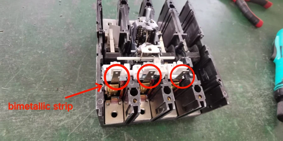
The thermal element is brilliantly simple. In traditional thermal-magnetic breakers, a bimetallic strip heats up and bends as current flows through it. The hotter it gets, the faster it bends—and the quicker the breaker trips. Electronic trip units replicate this behavior digitally, but the principle is the same: sustained overcurrent triggers protection after a calculated delay.
This thermal memory effect is crucial. If a motor runs at high load for hours, the thermal element “remembers” that heat. A subsequent overload will trip the breaker faster than it would if the system were cold, preventing cumulative damage that might not show up during short-term testing.
The inverse characteristic also allows for graduated responses: a 150% overload might take several minutes to trip, while a 300% overload could trip in under a minute. This helps the system differentiate between temporary disturbances and real threats.
Handling Motor Inrush Without Nuisance Trips
A common field problem is nuisance tripping when motors start. Large motors can draw 6–8 times their rated current for a few seconds. Without proper coordination, these inrush currents would constantly trip breakers, impacting operating.
Long-time protection avoids this by distinguishing between brief inrush currents during motor starts and sustained overloads that indicate a real problem. In simple terms, it trips only when high current lasts long enough to become harmful, but ignores short surges that are part of normal operation.
Stage 2: Short-Time Protection
Short-time protection is where coordination really comes into play. This stage handles moderate fault currents, but it does so with an intentional delay.
At first, many beginners will ask, “Why delay tripping during a fault?” The answer lies in system selectivity: letting downstream breakers clear their faults first prevents unnecessary trips upstream and keeps more of the system online.
Managing Moderate Faults with Intentional Delays
Think of a main breaker feeding several branch circuits, each with its own breaker. When a fault occurs on one branch, you want only that branch breaker to trip—not the main breaker, which would shut down everything else.
Short-time protection makes this possible by introducing a definite time delay, typically between 0.05 and 0.50 seconds. During this window:
-
If the downstream breaker clears the fault, the upstream breaker never trips.
-
If the downstream breaker fails, the upstream breaker acts as a backup.
Short-time protection handles fault currents that are too high for long-time protection but not severe enough to trigger instantaneous protection. Adjustable settings allow engineers to coordinate it effectively with downstream breakers, ensuring only the affected circuit is interrupted.
Benefits for System Coordination
Short-time protection does more than just prevent unnecessary trips—it also limits fault energy and reduces the risk of cascading failures or arc-flash hazards. When each device operates only within its designated zone, outages are minimized and energy released during fault clearing is controlled.
For example, in a manufacturing facility, a ground fault occurred in a motor control center (MCC) bucket. Without short-time coordination, the main breaker would have shut down dozens of motors. With proper short-time settings, the branch breaker tripped first, preventing the main breaker from shutting everything down and avoiding extensive downtime.
Electronic trip units enhance this coordination with definite and inverse time characteristics. Inverse curves follow an I²t relationship—that is, the trip speed depends on the current squared times time. Simply put, higher fault currents cause faster tripping, while lower currents allow a brief delay. This gives engineers flexibility to match downstream devices while keeping backup protection in place.
However, achieving this level of coordination requires circuit breakers with precise, adjustable trip units. Manufacturing these electronic components demands rigorous quality control to ensure they follow the trip curves exactly as designed.
Stage 3: Instantaneous Protection
Instantaneous protection is the emergency response team of circuit breakers. When fault currents reach dangerous levels that could destroy equipment or create immediate safety hazards, this stage bypasses all time delays and trips the breaker in milliseconds.
Unlike long-time or short-time protection, instantaneous protection responds purely electromagnetically. A magnetic coil inside the breaker activates the trip mechanism in 10 milliseconds or less, stopping high-current short circuits before they can harm the breaker, busbars, or connected equipment.

How Instantaneous Protection Works?
The principle is simple but powerful. Fault current flowing through the breaker’s magnetic coil generates a strong magnetic field. Once the field reaches a set threshold—called the pickup setting—it immediately releases the trip mechanism. There’s no thermal delay, no algorithms, no coordination checks—just pure, rapid electromagnetic action designed to stop dangerous currents.
In one case, a phase-to-ground fault in a motor control center produced a 15,000-ampere fault. Instantaneous protection cleared it in just 8 milliseconds, limiting damage to a few scorched busbars and blown fuses. In contrast, if the pickup setting is too high, fault currents can persist long enough to destroy switchgear sections and create severe arc-flash hazards.
Engineers can adjust the sensitivity of instantaneous protection to avoid nuisance trips from events like motor starts or transformer inrush, while still ensuring that real faults are caught immediately. Electronic trip units provide flexible adjustment, whereas older magnetic-only units often have fixed or more limited settings.
Protecting Breakers and Busbars
Instantaneous protection safeguards both downstream equipment and the breaker itself. High fault currents generate massive magnetic forces that can damage contacts, mechanisms, and enclosures. The faster these currents are interrupted, the less stress and damage occur.
Busbars are particularly vulnerable. Magnetic forces between conductors carrying high fault currents can bend, separate, or even break connections. Clearing faults within milliseconds minimizes these mechanical stresses and keeps the system intact.
The key challenge is setting the instantaneous element high enough to avoid nuisance trips—such as during motor starts, transformer inrush, or capacitor switching—but low enough to catch real faults. Proper discrimination ensures normal operations continue uninterrupted while dangerous events are stopped immediately.
How the Three Stages Work Together?
The real strength of three-stage protection lies in how all three stages coordinate to cover every kind of electrical fault. Each stage has its role, and together they create a complete safety system:
-
Long-time protection is like a patient analyst. It watches for slow, sustained overloads and lets minor, temporary fluctuations pass without interrupting normal operations.
-
Short-time protection acts as a tactical coordinator. It waits briefly to see if downstream breakers can clear moderate faults first, only stepping in if necessary.
-
Instantaneous protection is the emergency responder. It jumps into action immediately when a dangerous short circuit occurs, preventing serious equipment damage or safety hazards.
By working together, these three stages ensure that small issues don’t stop your system unnecessarily, moderate faults are handled without widespread outages, and severe faults are cleared instantly. The result is a system that balances safety, reliability, and uptime, without leaving gaps in protection.
Conclusion
Understanding three-stage protection isn’t just about breakers and currents—it’s about designing systems that anticipate problems before they happen. By thinking in layers and coordination, engineers create resilience, reminding us that safety and efficiency often come from careful planning rather than reactive fixes.
Implementing a robust protection scheme starts with choosing the right hardware. Whether you need standard thermal-magnetic breakers or advanced electronic LSI units, partnering with a capable manufacturer ensures your system performs as designed.