When I first stepped into the sample room years ago, I was surrounded by rows of mccbs—some small, some big. My supervisor asked me to “pick a 250-amp breaker.” I confidently pointed to the biggest one I could find. He chuckled, “You’re half right.” That moment stuck with me.
Back then, I thought bigger meant higher current. It sounded perfectly logical—until I learned how much more goes on inside a breaker. Each frame is carefully engineered to handle heat, magnetic forces, and fault energy far beyond what its size alone might suggest.
That early mistake taught me to look deeper and question my assumptions. In this field, understanding why something is built the way it is makes all the difference between simply connecting wires and truly mastering the invisible forces that keep power systems alive and safe.
What Is an MCCB Frame Size?
When I first started learning in this industry, I thought the frame size was just about how big the breaker looked. It turns out I was only half right.
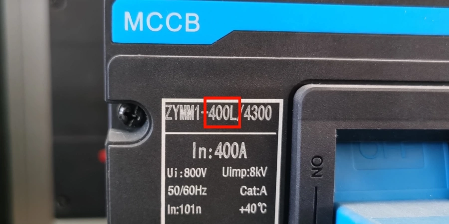
The frame size of a MCCB isn’t just about physical dimensions—it represents the maximum continuous current capacity that the breaker’s housing and internal parts can handle. Think of it as the shell rating of the device. This shell contains all the key components: the arc chutes, contact system, operating mechanism, and most importantly, the interchangeable trip units that determine when the breaker actually trips.
The frame size doesn’t tell you the trip setting. That’s a separate value entirely. The frame defines the upper limit—the maximum current the structure can safely carry and interrupt.
Why the Housing Matters?
The physical housing does more than just hold the parts together—it defines what the breaker can safely handle. The frame’s internal architecture—the thickness of the copper bars, the size of the arc chutes, and the contact surface area—is carefully engineered for its specific maximum current rating.
Having controlled the production and assembly process for nearly 30 years, we know that the "invisible" details matter most. Larger frames use heavier-duty materials and more robust mechanisms to deal with the heat and magnetic forces created by high currents. For example, a 1600 A frame has much thicker contact bars and larger arc chambers than a 250 A frame. This difference isn’t just about carrying more load current; it’s about surviving the massive electromagnetic forces that occur during a short circuit.

During equipment upgrades in many manufacturing facilities, it’s common to see engineers choose 400 A frames for circuits running at only 300 A. The idea is simple — plan for growth. Using a larger frame means future increases in load can be handled just by swapping in a higher-rated trip unit, without changing the breaker or the panel wiring. It’s a smart move that saves both time and money in the long run.
The Standardization Aspect
One thing that makes life easier is that frame sizes are standardized across most major manufacturers. Whether you are looking at Schneider, ABB, Siemens, or other brands, they generally follow the same frame size classifications. This makes panel design easier—you can plan your layout knowing the physical footprint, even if you haven’t decided which specific brand you’ll use.
This standardization is also why we have become a preferred MCCB component supplier for Tengen and Delixi. Our breakers are designed to fit standard panel layouts seamlessly, ensuring premium manufacturing quality without any compatibility headaches.
The standard also defines the interrupting capacity associated with each frame class—that is, the maximum fault current the breaker can safely stop without exploding or welding its contacts shut. Naturally, larger frames have higher interrupting ratings because they have more physical materials and wider contact gaps to extinguish the arc.
Frame Size vs. Trip Unit Rating
Even people who have been in the industry for years sometimes mix up frame size and trip unit rating. It’s an easy mistake because the two concepts are closely related—but they’re not the same thing.
In simple terms, the frame size sets the maximum capacity of the breaker’s physical shell—say, 250 A. The trip unit rating (also called the rated current, or In) is the actual current at which the breaker will trip under an overload—maybe 200 A, 160 A, or even 100 A.
The Flexibility Factor
What makes MCCBs so versatile is that a single frame can accommodate multiple trip unit ratings. For example, a 250 A frame might accept trip units anywhere from 100 A up to its full 250 A capacity. This modularity is a huge advantage for inventory management—and it is the core reason why many of our customers choose our MCCB SKD solutions.
Some distributors often stock only a few frame sizes while keeping a wide range of trip units available. When a specific rating is needed, the appropriate trip unit can simply be installed into the matching frame. This works like a modular system: the housing remains the same, while the “brains” can be swapped out as needed. By importing SKD parts from us and assembling locally, our partners significantly reduce stock pressure and import tariffs while responding faster to their local market needs.
For example, in a data center expansion project, 250 A frames were initially installed with 160 A trip units to match the existing server load. Two years later, when additional server units were added, the trip units were upgraded to 200 A without changing the panel layout, busbars, or cable terminations. The frames had been sized from the beginning to accommodate future growth.
Understanding the Relationship
Think of the trip unit as the engine of a car. It controls the “power” and decides how much force is applied—just like the trip unit decides when the breaker should trip. It can be thermal-magnetic (using a bimetallic strip and electromagnetic coil or electronic (using sensors and microprocessors). Either way, it’s the component that actually determines the current threshold.
The frame, on the other hand, is like the car’s chassis. It must be strong enough to handle the power generated by the engine—the thermal and mechanical stresses caused by high currents. You can’t put a 400 A “engine” (trip unit) into a 250 A “chassis” (frame)—the frame simply can’t handle it. The frame’s contact bars, current paths, and heat dissipation capacity are all designed for its rated current.

Here’s a practical example: if a circuit normally carries 180 A, you might choose a 250 A frame with a 200 A trip unit. The trip unit (engine) protects the circuit, while the frame (chassis) ensures the breaker can safely carry the current and withstand fault conditions. This combination gives both protection and the physical capacity to interrupt fault currents many times higher than the normal load.
Common Misunderstandings
I’ve heard many people say, “I have a 250 A breaker,” when they really mean a 250 A frame with a 160 A trip unit. This distinction matters because the actual protection level is 160 A, not 250 A. When coordinating protection devices or planning selective coordination, it’s the trip unit rating that counts—not the frame size.
Another misconception is thinking you can simply turn up the trip setting beyond the frame rating. Some adjustable trip units do allow fine-tuning within a range, but that range is always bounded by the frame capacity. An electronically adjustable trip unit rated for 100-250 A will only work in frames rated for at least 250 A. The trip unit and frame must match in their maximum ratings.
Standard Frame Sizes and Their Current Capacities
When you walk into any electrical supply house, and you’ll notice MCCBs organized by frame size. The industry has settled on a standard range that covers everything from small branch circuits to main distribution feeders.
The most common frame sizes you’ll find are 63 A, 125 A, 250 A, 400 A, 630 A, 800 A, 1250 A, and 1600 A. Each frame can handle a range of trip unit ratings, giving flexibility in how you protect your circuits.
| Frame Size (A) | Typical Trip Unit Range (A) | Common Applications |
|---|---|---|
| 63 | 10–63 | Small motor circuits, lighting panels |
| 125 | 16–125 | Branch circuits, small equipment feeders |
| 250 | 100–250 | Equipment feeders, sub-distribution |
| 400 | 250–400 | Large motors, distribution panels |
| 630 | 400–630 | Main distribution, heavy equipment |
| 800 | 630–800 | Large distribution boards, industrial mains |
| 1250 | 800–1250 | Primary distribution, building mains |
| 1600 | 1000–1600 | Service entrance, large facility mains |
Practical Selection Patterns
In my experience, 250 A and 400 A frames are the workhorses of commercial and light industrial settings. They strike a sweet balance between cost, size, and capacity. You’ll often see 250 A frames protecting HVAC systems, kitchen equipment, and other mid-sized loads, while 400 A frames are used for larger mechanical systems, elevators, and sub-distribution panels.
For residential and light commercial work, the 63 A and 125 A frames are the most common. These reliable “bread-and-butter” sizes handle branch circuits and small motors efficiently, which is why contractors keep them well-stocked—they’re always in demand.
Once you get into industrial plants, power stations, and large commercial buildings, 630 A and larger frames are more typical. These heavy-duty breakers handle main distribution and critical feeder circuits. As the frame size increases, so do the physical dimensions and cost, making careful sizing essential for both safety and efficiency.
Manufacturer Variations
Although frame size designations are standardized, manufacturers organize their product lines differently. Some use series names like DLM1, Compact NS, or Tmax to group frames with similar features. Within each series, you’ll find the standard frame sizes, but the specific features—like the type of trip units available, the interrupting ratings, or the accessory options—can vary.
For example, one manufacturer’s 250 A frame might have breaking capacities ranging from 25 kA to 70 kA depending on the model variant, while another manufacturer’s 250 A frame might max out at 50 kA. This is where reading datasheets carefully becomes important. The frame size tells you the current capacity, but you still need to verify the interrupting rating matches your fault current calculations.
While big brands offer extensive options, they also come with a premium price tag. This is where we steps in. We provide high-breaking capacity MCCBs that match these international frame standards, offering a cost-effective alternative for distributors without compromising on safety or performance.
Regional Differences
Frame size preferences can also vary by region. In North America, you might see more 800 A and 1200 A frames for certain applications, while in Europe and Asia, the 630 A frame is often preferred for similar uses. These differences usually relate to voltage systems, installation practices, and local standards—but the core concept of frame size remains the same.
The key takeaway: no matter the manufacturer or region, a frame size represents the maximum continuous current the breaker can safely handle, and each frame accommodates a specific range of trip unit ratings. Understanding this relationship helps you select the right breaker—ensuring safety without over-specifying and wasting money.
Why Frame Size Matters?
You might wonder why we can’t just pick a breaker based on the trip current we need and be done with it. In theory, that sounds simple. In practice, frame size affects far more than just current rating—it influences safety, reliability, installation, and even future flexibility.
Frame size directly impacts three key performance areas: interrupting capacity, thermal management, and physical compatibility with your electrical system. Getting any of these wrong can lead to nuisance tripping, premature failure, or, worst of all, a breaker that fails to protect when you actually need it.
Interrupting Capacity and Fault Handling
When a short circuit occurs, current can surge to tens or even hundreds of times the normal load current in milliseconds. The breaker must interrupt that current without destroying itself. Larger frames have higher interrupting capacities because they use more robust contact systems and larger arc chutes.
Here’s what actually happens during a fault: massive electromagnetic forces try to push the contacts apart—or weld them together—and an arc forms that must be extinguished safely. Larger frames have greater physical materials, wider contact gaps, and more arc chute plates to divide and cool the arc. This isn’t just theory—Smaller frames can fail severely under high fault currents, while properly sized larger frames handle the same conditions without damage.
The interrupting rating, expressed in kA (kiloamperes), can range from about 10 kA for small frames up to 150 kA for the largest ones. Your chosen frame must be rated above the prospective short-circuit current at that point in your system, or you risk creating a serious safety hazard.
Thermal Stability and Heat Dissipation
Whenever current flows, it generates heat—it’s basic physics. The real question is whether your breaker can dissipate that heat fast enough to stay within safe limits. Larger frames naturally have more surface area and thermal mass, allowing them to shed heat more effectively.
In some installations, smaller frames operate near their limits in hot environments—such as mechanical rooms with poor ventilation or panels exposed to direct sunlight. Under these conditions, breakers may trip time to time even though the load current remains within the rating. The problem isn’t overcurrent, it’s that the breaker can’t cool down enough. Upgrading to the next frame size, which handles heat better, usually fixes the issue.
The thermal time-current characteristic of a breaker depends partly on frame size. A 200 A trip unit in a 250 A frame will perform differently than a 200 A trip unit in a 400 A frame under sustained near-rated loads. The larger frame provides more margin and operates cooler, which can extend component life and reduce nuisance trips.
Physical Dimensions and Panel Design
Frame size also defines the physical footprint of the breaker—its height, width, and depth. This matters enormously when designing or retrofitting panels. Standard panel enclosures are built around specific mounting dimensions and busbar spacing for each frame size.
When upgrading from 250 A to 400 A frames, it’s common to discover that the existing panel cannot accommodate the larger breakers. The busbar spacing and mounting centers may not align, and the available depth might be insufficient. In such cases, an additional panel section or a redesign is often required—something that proper planning during the design phase could easily prevent.
Accessory Compatibility
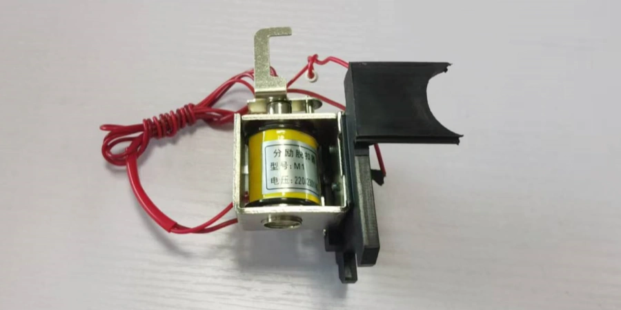
Modern MCCBs often include accessories like shunt trips, undervoltage releases, auxiliary contacts, alarm switches, and communication modules. Many of these accessories require minimum frame dimensions to physically fit. You can’t mount certain accessories on smaller frames simply because there’s no room.
| Accessory Type | Minimum Typical Frame | Purpose |
|---|---|---|
| Shunt trip release | 125 A | Remote trip via control signal |
| Undervoltage release | 125 A | Trips on voltage loss |
| Auxiliary contacts | 63 A | Status indication or signaling |
| Motor operator | 250 A | Remote switching |
| Communication module | 250 A | SCADA integration or monitoring |
I’ve also seen people who added control integration late in their projects, only to find that the breakers couldn’t accommodate the required accessories. This meant they had to replace breakers—or even entire panels—at significant cost. A little foresight in frame selection could have prevented all of that.
Future-Proofing and Flexibility
This is where experience really shows value. Selecting a frame size that matches your current trip requirement exactly might save a few budget at first, but it eliminates flexibility later. If loads grow (and they often do), you’ll be forced to replace entire breakers instead of just swapping trip units.
A smarter approach is to allow some headroom. For example, if you need 200 A protection today but there’s any possibility of growth, choose a 400 A frame with a 200 A trip unit. When the load increases, you can upgrade to a 300 A or 350 A trip unit without touching the wiring, busbars, or panel. The small extra cost of a larger frame is almost always cheaper than replacing breakers later—especially when you consider downtime and labor.
Frame size isn’t just a technical specification—it’s a decision that affects safety, performance, installation and future flexibility. Choosing wisely means looking beyond today’s requirements to consider fault conditions, heat, space, and what your system might need tomorrow.
Conclusion
Choosing the right MCCB frame size isn’t just about numbers—it’s about foresight. Every breaker you select shapes how your system grows, adapts, and stays safe. But technical specs are only half the battle; the quality of the manufacturing behind those specs is what keeps the lights on.
Whether you need a specific frame size for a finished project or an SKD solution to streamline your own assembly line, Sincede is ready to help. With 26 years of manufacturing experience, we control the entire chain—from mold making to final testing—ensuring you get consistent quality at a competitive factory price.
Don’t compromise on your supply chain. Contact us today to discuss your circuit protection needs.