After working around breakers for years, I’ve come to see MCCBs and ACBs not as rivals, but as complementary tools serving different roles in an electrical distribution system. Each has its own strengths, and understanding those strengths can make the difference between a well-balanced, reliable installation and one prone to unnecessary cost or downtime.
The differences are not just technical—they influence practical decisions every day. From selecting the right panel layout to planning future expansions, choosing between an MCCB and an ACB affects installation space, maintenance routines, and overall project budget.
Experience has taught me that the right choice often depends on the specific situation and the demands of the system. What works perfectly in one installation may not be ideal in another, and understanding the nuances can save time, cost, and headaches down the line.
Design and Maintenance
Here’s a breakdown of the most important distinctions, explained in a way that reflects how these devices are actually used in the field.
| Feature | MCCB | ACB |
|---|---|---|
| Construction | Molded, sealed case | Open or semi-enclosed frame |
| Typical Current Range | 10–1,600 A (up to 3,200 A) | 400–6,300 A |
| Breaking Capacity | 36–100 kA @ 415 V | 65–150 kA @ 415 V |
| Arc Quenching | Air within sealed case | Air with external arc chutes |
| Trip Unit | Thermal-magnetic or electronic | Almost always electronic |
| Mounting | Fixed (DIN rail or panel) | Fixed or draw-out |
| Maintenance | Low; usually replaced | Serviceable; components accessible |
| Typical Location | Feeders, sub-distribution | Main incomers, bus-ties |
Physical Size and Construction Philosophy
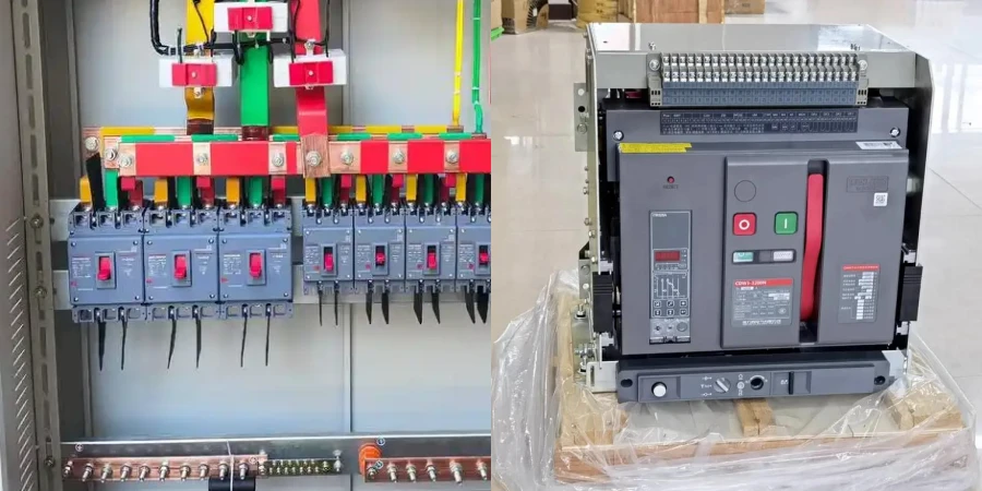
An MCCB’s molded case defines its design. Everything is enclosed in a compact housing that you can’t easily open or service. This design keeps manufacturing costs down, reduces the physical footprint, and makes installation straightforward—mount it, wire it, and move on. But there’s a trade-off: if something goes wrong internally, you’re typically replacing the entire unit rather than repairing it.
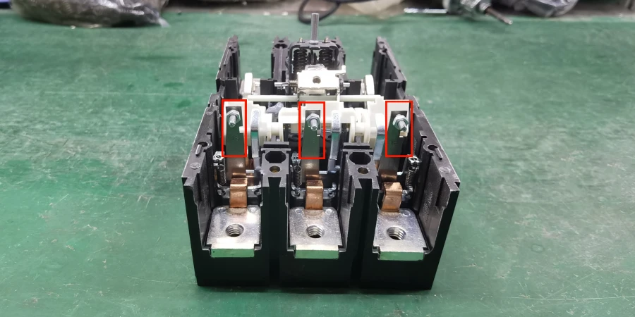
ACBs follow a very different philosophy. The open frame construction allows much better access to contacts, arc chutes, and mechanisms. I’ve watched technicians open up ACBs during routine maintenance to inspect contact wear, clean arc chutes, and test operating mechanisms—all things you simply can’t do with an MCCB. This serviceability matters in critical applications where you want to extend equipment life and minimize replacement costs over decades of operation.
Current Ratings and Breaking Capacity
Understanding current ratings and breaking capacity are where theory meets real-world design. I’ve been in enough project meetings with my customers to know that these numbers aren’t just lines on a datasheet—they’re the basics of safety, reliability, and proper system coordination. Get them wrong, and you’re either over-spending on equipment you don’t need or, much worse, installing protection that will fail when you need it most.
Continuous Current Ratings
The continuous current rating tells you how much current a breaker can carry indefinitely without tripping or overheating. For MCCBs, this typically starts around 10–16 A for small branch circuit protection and scales up through common sizes like 63 A, 100 A, 250 A, 400 A, 630 A, 800 A, 1,000 A, and 1,600 A. Some manufacturers offer frames up to 2,500 A or even 3,200 A, though these are less common and often compete directly with smaller ACBs in terms of both size and price.
ACBs take over where MCCBs start to run out of room. While you can find ACBs rated as low as 400 A, they’re really designed for the 800 A to 6,300 A range, where main service incomers and large feeders live. A typical power control center might use a 3,200 A or 4,000 A ACB as the main incomer, feeding several 1,600 A or 2,000 A ACBs for bus sections or major feeders. Those, in turn, feed distribution boards protected by MCCBs of various sizes.
One thing I learned from the engineers in my team is that you don’t just pick a breaker based on normal load current. You have to account for starting currents (especially for motors), future load growth, temperature derating, and coordination with upstream and downstream devices. A 400 A feeder might actually need a 630 A breaker if you’re running close to capacity and need margin for motor starting or anticipated expansion.
Breaking Capacity
Breaking capacity—also called interrupting capacity or short-circuit rating—is the maximum fault current a breaker can safely interrupt without catastrophic failure. This is one of the most critical safety parameter. If a short circuit occurs and the prospective fault current exceeds the breaker’s breaking capacity, the result can be violent failure, with a real risk of fire, explosion, and serious injury.
MCCBs are rated based on their frame size and design. A typical MCCB breaking capacity might be 36 kA, 50 kA, 65 kA, 85 kA, or 100 kA at 415 V. These values come from standardized tests and represent the maximum the breaker is designed to handle. In practice, you want some margin—installing a 50 kA breaker on a system with a calculated fault level of 48 kA is cutting it too close.
ACBs generally offer higher breaking capacities, often in the 65–100 kA range as standard, while high-performance versions can reach 120 kA or even 150 kA. This extra capacity isn’t overkill. At utility service entrances, transformer secondary locations, and main distribution points, fault levels can be extremely high due to the low source impedance. ACBs are built with stronger structures and more advanced arc-extinction systems specifically to deal with these severe conditions.
Frame Size
This is a point that confused me early on: two breakers with the same current rating can have completely different breaking capacities. The reason is frame size and internal design. For example, you might have a 400 A MCCB rated for 50 kA and another 400 A MCCB in a larger frame rated for 85 kA. The difference isn’t how much current they carry in normal operation—it’s how effectively the frame can control and extinguish an arc during a fault. (Related Reading: A Simple Guide to Understanding MCCB Frame Sizes)
| Breaker Type | Frame Size | Current Range | Typical Breaking Capacity @ 415V |
|---|---|---|---|
| MCCB | Small | 10–100 A | 25–36 kA |
| MCCB | Medium | 125–400 A | 36–65 kA |
| MCCB | Large | 630–1,600 A | 50–100 kA |
| ACB | Standard | 800–2,000 A | 65–100 kA |
| ACB | High-Performance | 2,500–6,300 A | 85–150 kA |
This table is simplified, but it shows how ratings generally scale. The key is to match the breaker to both the normal load current and the prospective fault current at its location in the system.
Service Breaking Capacity(Ics) vs. Ultimate Breaking Capacity(Icu)
The ultimate breaking capacity (Icu) is the maximum fault current the breaker can interrupt, but after doing so, the breaker may not be fit for further service—it’s essentially sacrificed itself to protect the system. The service breaking capacity (Ics), on the other hand, is typically a percentage of Icu—often 50%, 75%, or 100%, depending on the breaker—and represents the fault level the breaker can interrupt multiple times while remaining usable.
ACBs typically have an Ics that is closer to their Icu than MCCBs do, reflecting their more robust construction. In critical places, you want a breaker where Ics equals or nearly equals Icu, because you need confidence that even after clearing a major fault, the breaker is still reliable for continued operation. IEC 60947-2, the standard governing low-voltage circuit breakers, defines these categories and test requirements clearly, and reputable manufacturers publish both ratings so you can make informed decisions. (Related Reading: Icu and Ics on Circuit Breakers: What You Need to Know)
Protection Features Comparison
Protection is the whole reason circuit breakers exist, so understanding what each type can and can’t do really matters. When I first started learning about this stuff, I thought protection was simple—too much current, breaker trips, problem solved.
It took actual experience seeing different installations and talking to application engineers to appreciate just how sophisticated modern protection has become, especially in ACBs.
Basic Protection Functions
Both MCCBs and ACBs protect against two fundamental fault types: overloads and short circuits. Although they’re often mentioned together, they behave very differently and require distinct protection responses.
Overload protection covers moderate overcurrent conditions, typically around 120–200% of the rated current. These occur when circuits are overloaded or motors run under sustained mechanical stress. The risk is long-term overheating rather than immediate failure, so breakers use an inverse-time characteristic—minor overloads are tolerated briefly, while higher overloads trip faster to prevent thermal damage.
Short-circuit protection addresses severe faults caused by conductor-to-conductor or conductor-to-ground contact. Fault currents can reach tens of kiloamperes and generate extreme thermal and magnetic stress almost instantly. To limit damage, breakers rely on instantaneous or very short-time tripping, typically operating within a few tens of milliseconds.
Thermal-Magnetic vs. Electronic Trip Units
Traditional MCCBs use thermal-magnetic trip units. The thermal element is a bimetallic strip that bends when heated by current passing through it; when it bends far enough, it releases a latch that trips the breaker. This provides the inverse-time overload protection—higher currents heat the strip faster, causing quicker tripping. The magnetic element is a solenoid coil that generates magnetic force proportional to current; above a certain threshold (the instantaneous trip setting), the magnetic force is strong enough to directly trip the breaker within milliseconds.
This approach is proven, reliable, and cheap. But it has limits. The trip points aren’t very adjustable—you might have a few discrete settings or limited adjustment screws, but you can’t fine-tune curves precisely. You also don’t get detailed information about what happened or any diagnostic data.
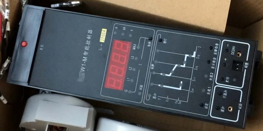
Electronic trip units, common in modern MCCBs and essentially standard in ACBs, work differently. They use sensors to measure current and microprocessors to apply programmable protection logic. This gives you:
-
Adjustable long-time protection (overload) with selectable pickup currents and time delays
-
Short-time protection with adjustable current and time settings for coordination
-
Instantaneous protection for severe faults
-
Ground-fault protection with separate sensitivity and time settings
-
Multiple curve shapes to suit different load types
An application engineer once explained to me that electronic trip units completely changed coordination. Before, you had to carefully select breaker frame sizes and fixed settings to achieve selectivity. With electronic units, you can fine-tune protection curves to coordinate precisely with upstream and downstream devices, getting better discrimination without over-sizing equipment.
Advanced Protection in ACBs
Where ACBs really stands out is in advanced protection and monitoring features. A typical ACB electronic trip unit includes everything an MCCB has, plus:
-
Zone-selective interlocking (ZSI): Breakers communicate with each other via control wiring. When a fault occurs, downstream breakers signal upstream devices to delay tripping. If the downstream breaker clears the fault quickly, the upstream ACB stays closed and the rest of the system remains energized. If the downstream device fails to clear the fault, the upstream ACB trips after a short delay. This provides excellent selectivity without the long time delays that traditional coordination requires.
-
Harmonic monitoring: Modern facilities with lots of electronic loads (variable frequency drives, LED lighting, computers) generate harmonic currents that can cause overheating and equipment problems. ACB trip units can monitor total harmonic distortion and neutral current, giving operators eary warning problems turn into failures. (Related Reading: How EMI Affects Circuit Breakers Performance?)
-
Phase imbalance detection: Unbalanced loading between phases can damage motors and transformers. ACBs can detect and alarm on excessive imbalance, or even trip if it becomes severe.
-
Metering and energy logging: Many ACBs include full power metering—voltage, current, power factor, energy consumption—which can be incredibly valuable for energy management and trending analysis.
-
Communication protocols: Modbus, Profibus, Ethernet/IP, and other industrial protocols allow ACBs to integrate into supervisory control systems. Operators can monitor breaker status, protection settings, metered values, and alarms from a central control room, and in some cases can remotely control breakers (though this requires careful safety considerations).
Ground-Fault and Earth-Leakage Protection
This deserves special attention because it’s often misunderstood. Standard overcurrent protection trips when line currents exceed thresholds, but it may not detect ground faults where relatively small current flows to ground through damaged insulation or accidental contact. Such faults can still cause fires, equipment damage, and electrical shock hazards without ever triggering overcurrent protection.
Both MCCBs and ACBs can include ground-fault protection, but the level of capability is different. In MCCBs, it’s often an optional add-on with limited adjustability—you might get fixed sensitivity levels like 30 mA, 300 mA, or a few amperes. In ACBs, ground-fault protection is usually built into the electronic trip unit with full adjustability of both pickup levels and time delays that can be coordinated with the system grounding method.

| Protection Feature | Standard MCCB | Electronic MCCB | ACB |
|---|---|---|---|
| Overload (Long-time) | Fixed/Limited adjustment | Adjustable | Fully adjustable |
| Short-circuit (Instantaneous) | Fixed/Limited adjustment | Adjustable | Fully adjustable |
| Short-time Delay | Not available | Available | Standard |
| Ground-fault | Optional, basic | Optional, adjustable | Standard, fully adjustable |
| Phase Imbalance | Not available | Rarely available | Common |
| Harmonic Monitoring | Not available | Not available | Available |
| Energy Metering | Not available | Rarely available | Common |
| Communication | Not available | Optional | Standard or optional |
| Zone Interlocking | Not available | Rarely available | Common |
This table simplifies things a bit—there’s a lot of variation between different manufacturers and product lines—but it shows the general trend.
As you move from basic MCCBs to electronic MCCBs to ACBs, protection becomes more sophisticated, adjustable, and integrated with broader facility management systems.
Conclusion
Electrical protection works best when it fits the situation, not just the specs. Knowing how MCCBs and ACBs behave in practice helps you make decisions that balance safety, efficiency, and cost. Good choices today make installations easier to manage and more resilient tomorrow.