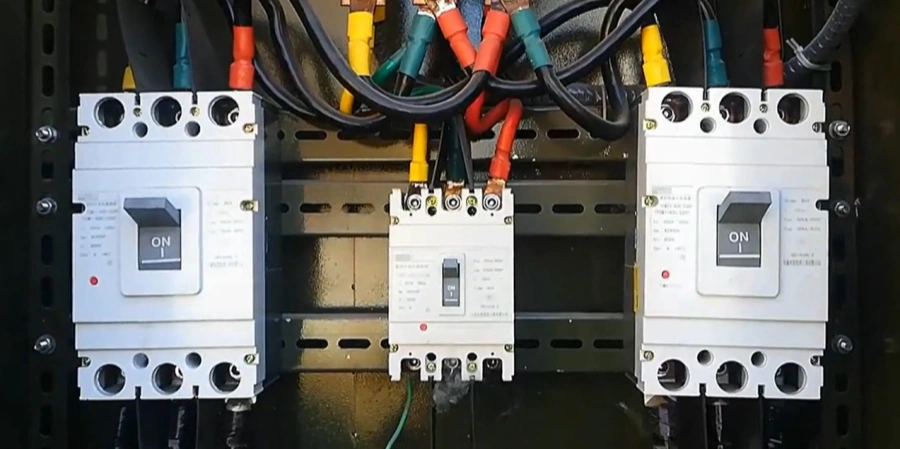
When you open an electrical panel on a busy factory floor, most of the components blend into the background. Yet one device quietly does more than its size suggests: the Molded Case Circuit Breaker, or MCCB. It handles faults you might never notice until something goes wrong.
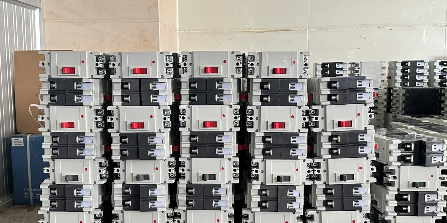
Having manufactured MCCBs for over 26 years at Sincede, we know that it’s easy to take them for granted. They rarely fail, require little attention, and keep systems running smoothly. But their reliability comes from careful design and precise engineering—from the internal mold making to the final assembly—making them more than just switches.
Understanding how MCCBs operate and choosing the right one for the job isn’t just technical—it’s practical. A well-selected breaker prevents unnecessary downtime, protects equipment, and gives confidence that the system will keep running safely, day after day.
What Is a Molded Case Circuit Breaker (MCCB)?
When I first saw MCCBs, they seemed a bit intimidating—big, heavy devices sitting inside industrial panels, clearly handling serious power. But once you understand what they do, they’re actually pretty straightforward.
A Molded Case Circuit Breaker is a protective device that automatically cuts off electrical power when something goes wrong in your circuit. Think of it as a built-in safety switch that triggers during overcurrent conditions, short circuits, or ground faults. The "molded case" refers to its housing—a tough, insulated shell made from materials like thermoset composite resin or glass-polyester that protects all the internal components.
What makes MCCBs different from the small circuit breakers you see in residential panels is their scale and capability. MCCBs can handle much higher currents—anywhere from 15 A up to 2,500 A—and they can interrupt much higher fault currents without getting damaged.
The Core Purpose
MCCBs serve a dual role in electrical systems:
-
First, they protect your equipment and wiring from damage caused by excessive current. When a motor overloads or a short circuit occurs, the MCCB detects the problem and breaks the circuit before cables melt or equipment burns out.
-
Second, they act as manual disconnection switches, allowing maintenance personnel to safely isolate circuits for service work.
The breaking capacity of these devices ranges from 25kA to 200kA, which tells you how much fault current they can safely interrupt. In industrial settings where available fault currents can be extremely high, this rating becomes critical.
Key Operating Characteristics
In practical terms, several features set MCCBs apart. Their voltage ratings cover common industrial systems: 120V, 240V, 415V, 480V, and 600V.
They also use different types of trip mechanisms—thermal-magnetic for standard applications, electronic for more precise control, and hybrid systems that combine both. The adjustability is something I really appreciate; unlike fixed MCBs, you can fine-tune MCCB settings to match specific equipment needs.
They’re also built to survive tough environments. The molded case protects against dust, moisture, and physical impact—exactly what you need in manufacturing plants, outdoor setups, or anywhere conditions are less than ideal. I’ve seen MCCBs keep working reliably in places where lesser equipment wouldn’t last long.
How MCCBs Work?
Understanding how MCCBs actually protect circuits has helped me explain their value to less-experienced buyers why these breakers cost more than the basic ones. The protection isn’t magic—it’s clever engineering combining multiple detection methods.
MCCBs use three integrated protection mechanisms that work together to safeguard electrical systems. Each mechanism targets different types of faults, creating layers of protection that catch problems—thermal, magnetic, and ground fault detection working as a coordinated team.
Thermal Protection for Overloads
The thermal element uses a bimetallic strip—two different metals bonded together that expand at different rates when heated. When current flows through the circuit, it generates heat. Normal operating current produces mild warmth, but when current exceeds safe levels, the strip heats up and bends due to unequal thermal expansion. This bending physically triggers the trip mechanism, opening the contacts and breaking the circuit.
The interesting part about thermal protection is its inverse-time characteristic. Higher overcurrents cause faster tripping because they generate more heat more quickly. This behavior is actually beneficial—it allows temporary current spikes, like when motors start up and briefly draw several times their normal running current, to pass through without nuisance tripping. A sustained overload, however, builds enough heat to trip the breaker before damage occurs.
Magnetic Protection for Short Circuits
Short circuits are different animals entirely—instead of gradual overloads, you get sudden, massive current surges that can weld contacts and vaporize conductors in milliseconds. The magnetic element handles these situations with an electromagnetic coil around the current path.
During a short circuit, current can jump to five, ten, or fifteen times the rated value almost instantly. The coil generates a powerful magnetic field in the coil, which pulls a metal lever or armature. Unlike the thermal element’s gradual response, the magnetic action is nearly instantaneous—we’re talking milliseconds. This speed really matters because short circuit currents can cause catastrophic damage incredibly quickly.

Arc Extinguishing and Ground Fault Detection
When MCCB contacts separate under load, an electrical arc forms between them—basically a sustained spark that can damage the contacts and release dangerous energy. The arc extinguishing system uses arc chutes or chambers that split and cool the arc, extinguishing it safely within milliseconds. Without this system, the arc could persist, defeating the whole purpose of opening the circuit.
Some MCCBs include ground fault protection, which detects current leaking to ground rather than returning through the normal circuit path. This happens when insulation fails or live conductors contact grounded metal. The system compares current flowing out through the hot conductors versus current returning through the neutral—any imbalance indicates current leaking to ground, triggering a trip.
In practice, these protection mechanisms work together seamlessly. The thermal element handles sustained overloads, the magnetic element catches sudden faults, the arc extinguisher ensures safe interruption, and ground fault detection provides an additional safety layer. It’s this combination that makes MCCBs so reliable in protecting expensive industrial equipment.
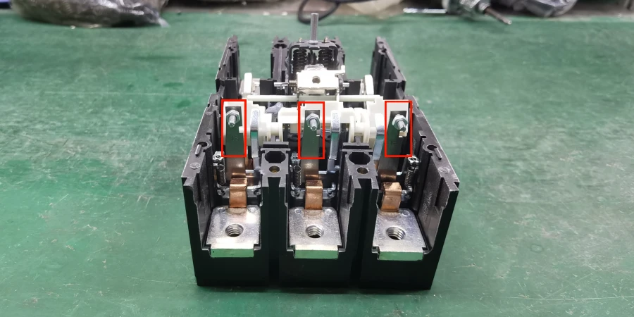
💡 Manufacturer’s Insight: The Importance of Component Quality
Understanding these internal mechanisms highlights why the quality of individual components matters. For local panel builders and switchgear manufacturers who prefer MCCB SKD Solutions to reduce import tariffs and assembly costs, the precision of the arc chutes and the purity of the contact materials are critical.
At Sincede, we don’t just assemble breakers; we manufacture the core components in-house. Whether you are sourcing complete breakers or looking for SKD kits to assemble in your local factory, ensuring the integrity of these internal parts is our standard.

Types of MCCBs: Thermal-Magnetic vs. Electronic
When specifying MCCBs for projects, one of the first decisions is choosing the trip unit type. This choice impacts protection characteristics, precision, features, and cost—and it’s not always obvious which type suits a particular application best.
Thermal-magnetic MCCBs represent the traditional technology—electromechanical devices that have protected industrial systems for decades. Electronic trip MCCBs bring digital monitoring and control to circuit protection. Both have their place, and I’ve seen both types working reliably in appropriate applications.
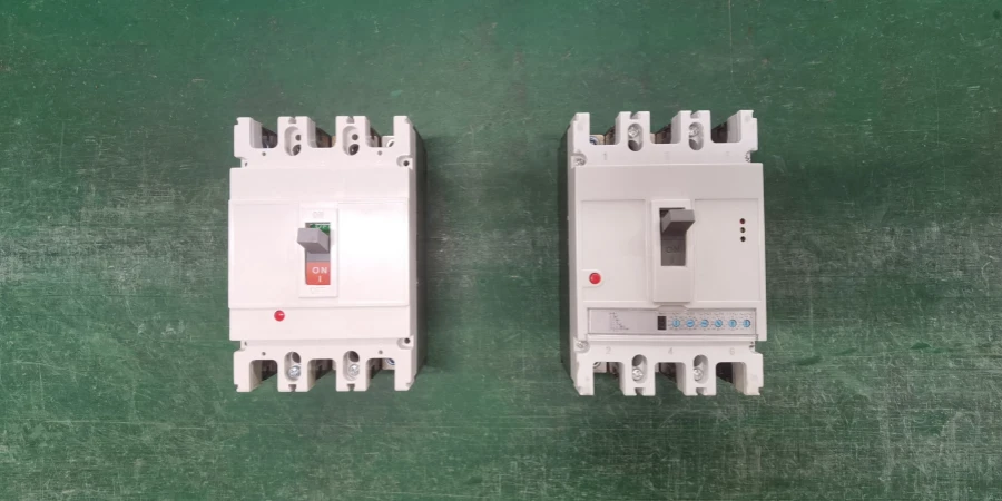
Thermal-Magnetic MCCB
As we mentioned in the previous chapter, these breakers combine physical thermal and magnetic elements in one device. The beauty of this design is its simplicity and reliability—there are no electronics to fail, no power supplies required, and the protection operates purely based on physical principles.
Thermal-magnetic MCCBs work particularly well in applications with high inrush currents. Manufacturing facilities with many motors, welding equipment, or transformers benefit from this tolerance. The magnetic setting can often be adjusted—fixed, adjustable, or multi-position settings that let you tune the short circuit response to your specific system.
The main limitation is precision. Thermal elements are affected by ambient temperature—a breaker operating in a 40°C panel room won’t trip at exactly the same current as one in a 20°C environment. The trip curves have relatively wide tolerance bands compared to electronic units. For most applications this doesn’t matter, but precision-critical situations might need something better. (Related Reading: How Does Ambient Temperature Affect Circuit Breakers?)
Electronic Trip MCCB
Electronic trip units use current transformers to monitor circuit current, with microprocessors analyzing that data in real-time. This digital approach provides much greater precision and features than thermal-magnetic designs. The trip curves are programmable, meaning you can select exactly the protection characteristic that matches your load.
What impresses me about electronic MCCBs is the monitoring capability. These devices can display current, voltage, power factor, energy consumption, and other parameters. They can communicate via standard industrial protocols, feeding data to building management systems or maintenance software. This visibility helps identify developing problems—like a motor gradually drawing more current over weeks, indicating bearing wear or other developing issues.
The protection features go beyond basic overcurrent protection. Electronic units can provide ground fault protection with adjustable sensitivity, short-time delays for coordination with downstream devices, and even harmonic monitoring in some models. You can program multiple protection curves, set precise trip points, and adjust time delays with much finer granularity than mechanical breakers allow.
Practical Selection Guidance
| Aspect | Thermal-Magnetic | Electronic Trip |
|---|---|---|
| Cost | Lower ($100-$1,500) | Higher ($500-$4,000+) |
| Precision | Moderate, affected by temperature | High, stable across conditions |
| Features | Basic protection | Advanced monitoring, communication |
| Reliability | Proven electromechanical design | Depends on electronics quality |
| Maintenance | Minimal | May require periodic calibration |
| Best For | General industrial, motor circuits | Critical facilities, smart buildings |
For standard industrial setting without special requirements, thermal-magnetic MCCBs offer excellent value. They’re robust, affordable, and field-proven over decades. We recommend them for general machinery protection, standard motor circuits, and situations where monitoring isn’t critical.
Electronic MCCBs make sense in several scenarios. Critical facilities like hospitals or data centers benefit from the monitoring and precision. Smart buildings with integrated building management systems need the communication capabilities. Applications requiring precise coordination with other protective devices benefit from the programmable curves. And situations where you need detailed electrical data for energy management or predictive maintenance justify the higher cost.
One thing I’ve learned: don’t assume more technology is always better. I’ve seen customers spend premium prices for electronic MCCBs, then never use any of the advanced features. Match the technology to your actual needs, and you’ll get better value and reliability.
MCCB Ratings: Understanding Current and Breaking Capacity
One of the most confusing aspects for people new to MCCBs is learning all the ratings labeled on the device. I’ve watched engineers explain these specifications to beginners many times, and the confusion usually comes from not understanding what each rating actually means in practical terms.
MCCB ratings tell you what the device can handle under both normal operation and fault conditions. Get these wrong, and you either have inadequate protection or a breaker that trips unnecessarily, disrupting operations. Here are the key ratings you need to understand.
Rated Current (In)
The rated current is the maximum continuous current an MCCB can carry indefinitely without tripping under normal ambient conditions. You’ll see values like 100A, 250A, 630A, or higher. This number is the breaker’s capacity—not the actual operating current of your circuit.
Standard MCCB ratings follow specific increments: 15A, 20A, 32A, 50A, 63A, 100A, 125A, 160A, 200A, 250A, 400A, 630A, 800A, 1000A, 1250A, 1600A, 2000A, and 2500A. These standardized values make selection easier and ensure compatibility between different manufacturers.
A common pitfall is forgetting that rated current assumes a reference temperature, usually 40°C ambient. If you’re installing MCCBs in a hot environment—say, an outdoor panel in direct sunlight or a poorly ventilated enclosure—the breaker might not actually carry its full rated current continuously. Heat is the enemy of electrical equipment, and MCCBs are no exception.
Breaking Capacity
There are two parameters that determine a breaker’s breaking capacity: Ultimate Breaking Capacity (Icu) and Service Breaking Capacity (Ics).
Ultimate Breaking Capacity (Icu) is the maximum fault current a breaker can safely interrupt once. After interrupting a fault at this level, the breaker might be damaged and unusable anymore.
Service Breaking Capacity (Ics), in contrast, indicates the fault current level the breaker can interrupt repeatedly while remaining fully workable.
Ics is usually expressed as a percentage of Icu, typically 75% to 100%. A breaker with 50kA Icu and 100% Ics can interrupt 50kA faults multiple times and keep operating reliably. One with 75% Ics can interrupt 37.5kA repeatedly, but faults between 37.5kA and 50kA might damage it even though it successfully clears the fault.
For important applications where downtime isn’t an option, reliable breaking capacity is non-negotiable. This is why every Sincede MCCB undergoes rigorous testing in our laboratory to ensure the actual Icu and Ics ratings meet the specified standards. We guarantee that the breaker our customers install performs exactly as promised. (Related Reading: Icu and Ics on Circuit Breakers: What You Need to Know)
Voltage Ratings and System Compatibility
MCCBs are designed for specific voltage systems: 120V, 240V, 277V, 380V, 415V, 480V, or 600V AC. The voltage rating must match or exceed your system voltage—using a 480V-rated MCCB on a 600V system risks internal arcing and failure.
Most MCCBs often include a ±10% voltage tolerance, allowing safe operation within specified ranges. But that doesn’t mean you should stretch the limits.
| Rating Type | What It Means | Typical Values | Selection Rule |
|---|---|---|---|
| Rated Current (In) | Continuous capacity | 15A – 2,500A | ≥ 125% of continuous load |
| Breaking Capacity (Icu) | Maximum fault current | 10kA – 200kA | ≥ Available fault current |
| Service Capacity (Ics) | Repeatable interruption | 75% – 100% of Icu | Higher is better for critical apps |
| Voltage Rating | System voltage limit | 120V – 600V AC | ≥ System voltage |
| Frequency | AC frequency | 50Hz or 60Hz | Must match system |
Frame Size and Physical Considerations
Beyond electrical ratings, MCCBs come in different frame sizes, which are basically their physical dimensions. Higher-current MCCBs usually need bigger frames to fit in stronger internal parts and handle heat safely. Manufacturers often offer a range of frame sizes, with several current ratings available within the same frame series, which helps simplify panel design and makes future upgrades easier.
As current ratings increase, so do the size and weight of the breakers. For example, a 2000A MCCB is much larger and heavier than a 100 A unit. I remember the first time I saw high-current MCCBs on site—I was surprised by their size and weight. Proper mounting and support are important to ensure safe installation. (Related Reading: A Simple Guide to Understanding MCCB Frame Sizes)

Conclusion
Over the years, I’ve seen that a reliable MCCB is the backbone of industrial safety. Whether you are a distributor looking for finished products or a factory manager seeking SKD parts for local assembly, the source of your breakers determines the safety of your projects.
With 26 years of manufacturing excellence, Sincede is committed to delivering industrial-grade Low Voltage Circuit Breakers that stand the test of time.
Are you looking for a reliable supplier? Check out our MCCB solution or contact our team to discuss your project needs.