Previously, we talked about Ue and Ui, which help us understand the voltage levels and insulation performance of a circuit breaker during normal operating conditions. These are the basic values used when selecting equipment.
But in real power systems, not everything happens under steady conditions. Alongside normal voltage, there are also short and irregular electrical events that do not appear in everyday operation, but still need to be considered in system design and equipment selection.
These conditions are covered by another important parameter, known as Uimp, which is defined specifically to deal with this type of electrical stress in insulation coordination.
What Is Rated Impulse Withstand Voltage (Uimp)?
So, what exactly is Uimp?
Put simply, rated impulse withstand voltage(Uimp) is the peak voltage value of a specific impulse waveform that a circuit breaker can survive without breaking down.
In other words, it tells you how well a breaker’s insulation can handle a sudden, extremely short burst of high voltage.
It’s About Spikes, Not Steady-State Voltage
This is where I get confused when I first saw this parameter on the breaker nameplate. Uimp is not about the normal operating voltage running through your system day to day. It’s about those violent, momentary spikes — the kind you get from a lightning strike hitting nearby infrastructure, or from a large motor or transformer switching on and off in the same network.
These transient overvoltages last only microseconds, but they carry enough energy to damage insulation, create arcs across contacts, or permanently harm equipment. So even if a breaker is rated at 230V or even 690V for continuous use, it may still need to withstand a 6 kV or 8 kV impulse during its lifetime, depending on where it’s installed and what else is connected to the same circuit.
How Uimp Fits on a Datasheet?
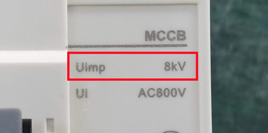
When you look at a circuit breaker’s datasheet, you’ll usually see Uimp listed alongside other insulation ratings like Ui (rated insulation voltage) and Ud (power frequency withstand voltage). These values are related, but they measure different things.
Uimp specifically focuses on peak transient performance, while Ui and Ud deal with continuous and short-term AC stress. For low-voltage applications, industrial circuit breakers commonly have a Uimp of 8 kV, while domestic types are more commonly rated at 6 kV.
Why Uimp Matters in Circuit Breakers?
You might wonder — if transient overvoltages only last a few microseconds, how much damage can they really do?
The answer, unfortunately, is way more than you think. And once you’ve seen what happens when a breaker’s insulation fails under an impulse, the importance of getting this rating right becomes very clear.
What Happens When the Rating Is Too Low?
When a circuit breaker faces a transient overvoltage that exceeds its Uimp rating, the insulation doesn’t always fail dramatically or all at once. Sometimes it’s a flashover — a sudden arc of electricity across a surface that should keep insulating. Other times it’s a puncture, where the voltage forces its way through the solid insulation material, creating a permanent path for current to follow.
Both cases are bad. A flashover can trip the system and cause an outage. A puncture, on the other hand, can lead to fire risks, or quietly weaken the breaker until it fails at the worst possible moment.

The Domino Effect on System Reliability
What makes inadequate Uimp especially problematic is its downstream effect. A single breaker failure from an impulse event doesn’t just affect that one device. Depending on how the system is wired, it can shut down entire circuits, halt production lines, or even trigger cascading failures across a panel.
In industrial environments, that kind of unplanned downtime is really expensive. In critical infrastructure — such as hospitals, data centers, emergency systems — it can be dangerous.
According to CIGRE reports, insulation breakdown accounts for over 20% of major circuit breaker failures at service voltage. That’s a significant share, especially when you consider that mechanical faults make up around 50% and control-related issues about 30%.
In other words, roughly one in five serious failures comes down to the insulation not being up to the job — and Uimp is the rating that defines that capability.
What Standards Say About It?
Standards like IEC don’t leave Uimp selection to guesswork. IEC 60664-1 defines overvoltage categories for low-voltage installations and links each category to specific Uimp requirements.
For example, equipment at overvoltage category IV — at the point of entry to a building, closest to the supply — requires a higher impulse withstand rating than equipment deeper in the installation at category II. The standard essentially connects a device’s position in the electrical system to the level of transient stress it’s likely to experience, and Uimp needs to match or exceed that level.
This isn’t just a box-ticking exercise. Selecting the right Uimp for the right application is one of the most practical ways you can do to improve long-term system reliability.
Uimp Values by Voltage Rating
Uimp isn’t a single fixed number.
It scales with the rated voltage of the equipment, and IEC standards clearly define this relationship. Once you see the values laid out, it starts to feel logical — higher system voltages are exposed to higher transient stress, so the insulation needs a correspondingly higher rating.
How IEC Standards Define the Numbers?
IEC 62271-100 and related standards specify the required lightning impulse withstand voltage (referred to as Up in medium-voltage contexts) based on the rated voltage Ur of the equipment.
The values below cover the medium-voltage range commonly used in switchgear and circuit breaker specifications:
| Rated Voltage Ur (kV) | Rated Lightning Impulse Withstand Up (kV peak) |
|---|---|
| 3.6 | 40 |
| 7.2 | 60 |
| 12 | 75 |
| 17.5 | 95 |
| 24 | 125 |
| 36 | 170 |
These values aren’t random. They are from decades of field experience, testing data and failure analysis that tell us what kind of impulse stress equipment at each voltage level is likely to face during its service life.
When a breaker is specified for a 12 kV system, a 75 kV impulse isn’t excessive — it’s simply the baseline requirement you’d expect to see for reliable performance.
Low-Voltage Equipment
For low-voltage applications — the kind most common in commercial buildings, factories, and residential systems — the numbers are much smaller, but the principle is the same. Overvoltage categories defined in IEC 60664-1 determine the required Uimp based on where the equipment is installed within the system.
| Overvoltage Category | Typical Location | Required Uimp (230/400V system) |
|---|---|---|
| Category IV | Supply entry point (meters, main switches) | 6 kV |
| Category III | Distribution boards, fixed industrial equipment | 4 kV |
| Category II | Household appliances, plug-in equipment | 2.5 kV |
| Category I | Protected electronic equipment | 1.5 kV |
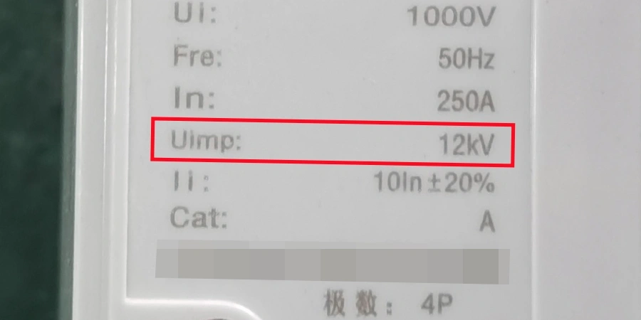
Industrial circuit breakers are typically in the range of 6 kV to 8 kV, while higher-performance MCCBs used at main distribution or demanding industrial environments can reach 10 kV or even 12 kV.
The difference exists because equipment closer to the incoming supply is exposed to higher and less filtered transient energy. As surges propagate through the installation and pass through protective stages, their intensity is reduced—so downstream equipment does not need to withstand the full impulse level.
Across Open Contacts: A Detail Worth Knowing
One specification that often gets less attention is the across-open-contact Uimp value. When a circuit breaker is open, there’s a gap between its contacts, and that gap needs to withstand impulse voltage too — sometimes at a higher level than the phase-to-earth requirement.
For certain high-voltage breaker specifications, this value can reach 1550 kV peak. While this may sound extreme, it becomes relevant during installation, switching operations, and maintenance scenarios, especially when one side of the equipment may still be energized while the other is isolated.
Understanding these values — and knowing which one applies to your specific application — is key part of getting a specification right the first time.
How Uimp Differs from Other Insulation Ratings?
On a typical circuit breaker datasheet, you’ll see at least three different insulation-related voltage ratings sitting next to each other: Uimp, Ui, and Ud.
They look similar, and they’re all measuring something about the breaker’s insulation capability — but they’re testing completely different things, and mixing them up leads to real specification errors.
Uimp vs. Ui
Ui is the rated insulation voltage — the maximum continuous voltage the breaker’s insulation is designed to handle during normal operating conditions. It defines the upper limit of the system voltage the breaker can be used in on a steady-state basis. So if a breaker has a Ui of 690V, that means the insulation is designed for continuous exposure up to 690V AC. (Related Reading: A Basic Intro to Rated Insulation Voltage in Circuit Breakers)
Uimp, by contrast, has nothing to do with continuous stress. It’s about a single high-energy spike that lasts only microseconds. The insulation doesn’t need to sustain that peak voltage — it just needs to survive it without breaking down.
These are fundamentally different types of stress on the material, and a breaker with a high Ui doesn’t automatically have a high Uimp, and the reverse is also true.
A simple way to think about it: Ui is like the weight a beam can carry every day, while Uimp is the sudden impact it must absorb without cracking. Both matter, but for different reasons.
Uimp vs. Ud
Ud (power frequency withstand voltage) is basically a "hold this pressure for a while" test.
During the test, an AC voltage (50 or 60 Hz) is applied for about one minute to check if the insulation can handle it without breaking down. The value is given as an RMS voltage, and it shows how well the breaker can deal with higher-than-normal voltage over a short period of time—like during a fault or a temporary overvoltage.
Uimp is very different. Instead of a steady voltage, it’s a sudden spike—the voltage jumps to a high peak and disappears almost instantly. This value is given as a peak voltage, and it shows whether the breaker can survive that quick shock.
So even though both are testing insulation strength, they focus on different situations:
-
Ud checks if the insulation can handle pressure over time
-
Uimp checks if it can survive a quick, high-voltage hit.
A good circuit breaker needs to pass both tests—so it can handle both steady stress and sudden spikes.
IEC’s Uimp vs. IEEE’s BIL
If you have dealt with equipment specified under both IEC and IEEE standards — which is common in export projects—you’ll come across BIL (Basic Insulation Level) as the IEEE equivalent part of Uimp. The core concept is the same: both measure a device’s ability to withstand a lightning impulse with a defined waveform and peak value.
The differences lie in how the tests are carried out:
| Aspect | IEC Uimp | IEEE BIL |
|---|---|---|
| Test waveform | 1.2/50 µs | 1.2/50 µs |
| Chopped wave test | Not required for all equipment | Required in some cases |
| Waveform tolerance | Defined by IEC 60060-1 | Defined by IEEE Std 4 |
| Environmental corrections | Standard atmospheric conditions | Includes temperature/humidity adjustments |
| Primary markets | International / European | North American |
Although the waveform itself is the same, procedural differences—especially around chopped wave testing and tolerance handling—mean you can’t always treat a BIL value as a direct substitute for Uimp without checking the details.
When specifying equipment for international projects, it’s worth confirming which standard applies and whether the available test reports align with that standard.
Why It Matters to Get These Straight?
If a procurement team selects a breaker based only on Ui and ignores Uimp, they may end up with equipment that performs well under normal conditions but is vulnerable to transient overvoltages—like those caused by lightning or switching events.
These issues don’t always cause immediate failure. Instead, the insulation may degrade over time, leading to premature breakdown months later under conditions that should have been safe.
Making sure Uimp, Ui, and Ud all match the installation category and system voltage isn’t over-specification—it’s simply doing the job properly.
Conclusion
Understanding Uimp helps you look beyond basic voltage ratings and focus on real electrical stress in a system. It plays a quiet but important role in equipment reliability. When selecting circuit breakers, considering impulse conditions alongside normal ratings leads to safer and more stable installations in the long run.