On the nameplate of a circuit breaker, you can usually see several different voltage values. We have already talked about rated voltage before. This time, we will look at another one that often causes confusion: rated insulation voltage, or Ui.
At first, it may look similar to the working voltage, since both are shown in volts. But in real use, they mean very different things. One shows how the breaker works, while the other shows how it is built to handle electrical stress.
This difference is easy to miss, especially when choosing or replacing equipment. However, it can quietly affect how reliable the breaker will be over time, especially when the system voltage is not always stable.
What Is Rated Insulation Voltage (Ui)?
Rated insulation voltage (Ui) is a number that shows how strong a circuit breaker’s insulation needs to be. According to IEC 60947-2, it is used as the basis for tests and design details like dielectric tests, clearances and creepage distances. In other words, it tells you the highest voltage the breaker’s insulation is designed and tested to handle safely.
It’s easy to mix this up with the breaker’s working voltage, but they are not the same. The breaker does not operate at Ui in normal use. Instead, Ui is a safety limit. It shows the maximum voltage the insulation can handle, giving the breaker extra protection when voltage rises above normal levels. (Related Reading: Understanding Rated Voltage in Circuit Breakers)
Not an Operating Voltage — An Insulation Benchmark
You can think of it this way. When engineers design a breaker, they need to make decisions about how far apart internal live parts should be, how long insulating surfaces between conductors must be, and what dielectric tests the product must survive during type testing. All of these decisions are based on a single reference point: Ui.
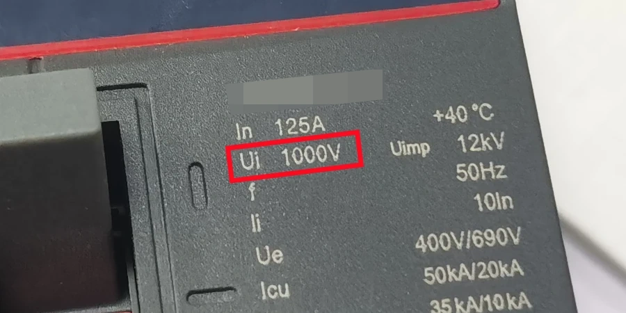
If Ui is set at 1000 V, it means every internal clearance, every creepage distance, and every dielectric test has been designed and verified against that level — not the 415 V or 690 V the breaker will actually see in service. That gap between Ui and actual operating voltage is not a mistake. It is the margin that keeps the breaker reliable when real-world conditions push voltage beyond normal levels, even briefly.
Why This Baseline Matters?
Without a clear insulation baseline, a breaker might pass every functional test in a controlled environment but fail in the field when exposed to switching surges or a temporary overvoltage. Ui helps prevent that. It forms the foundation of the entire insulation design and plays a key role in how safe and durable the breaker will be through its service life.
Why Ui Is Set Higher Than the System Voltage?
A question that often comes up among beginners is why standards require Ui values of 1000 V even for circuit breakers used in 415 V systems. At first, this can look like overengineering. But once you understand what electrical systems really experience in real-world conditions—not just what they are designed for on paper—the reason becomes much clearer.
Real Electrical Systems Are Not Always Clean
In theory, a 415 V AC system should always stay at 415 V. In reality, it rarely does. Voltage in real installations is constantly fluctuating, and certain events push it well beyond the nominal level, even if only for a very short time.
The most common culprits are:
-
Switching surges — when large inductive loads are switched on or off, the collapsing magnetic field generates a high-energy voltage spike that travels through the system.
-
Temporary overvoltages (TOVs) — these occur during load shedding, ground faults in high-impedance systems, or resonance conditions, and can keep voltage levels for longer than a transient spike.
-
Harmonic distortion — in systems with significant non-linear loads such as variable speed drives or UPS systems, harmonic currents distort the voltage waveform and create additional stress on insulation materials compared to a clean sine wave.
None of these events are unusual or rare. They are part of normal electrical system behavior, which means a circuit breaker’s insulation must be able to withstand them repeatedly without degrading.
The Insulation Margin — Why the Gap Exists
Setting Ui at 1000 V for a breaker used in a 415 V system creates a deliberate safety margin. This margin absorbs the additional voltage stress from the events described above without pushing the insulation to its limit.
Insulation systems do not fail suddenly—they degrade gradually over time — each overvoltage event that exceeds the design stress contributes to that aging process, even if it does not cause an immediate failure.
Over months or years of operation, a breaker with insufficient insulation margin may still appear to function normally during routine checks, while quietly accumulating damage that eventually leads to failure. A properly specified Ui helps prevent this slow, progressive degradation by providing enough headroom.
Typical Ui Values in the Field
In industrial and commercial low-voltage circuit breakers, Ui = 1000 V has become the main standard reference value, even for systems rated at 415 V or 690 V. Some older or lighter-duty devices may still use lower ratings, but modern LV switchgear has moved toward 1000 V as the default choice.
That said, lower Ui values such as 500 V, 630 V, 690 V, and in some cases 800 V still exist in real products. They are used in specific situations where the insulation stress is moderate and the system environment is relatively controlled.
-
230 V or single-phase distribution systems: Small circuit breakers and residential or light commercial devices often use Ui around 500 V. These systems usually have lower switching stress and fewer severe overvoltage conditions.
-
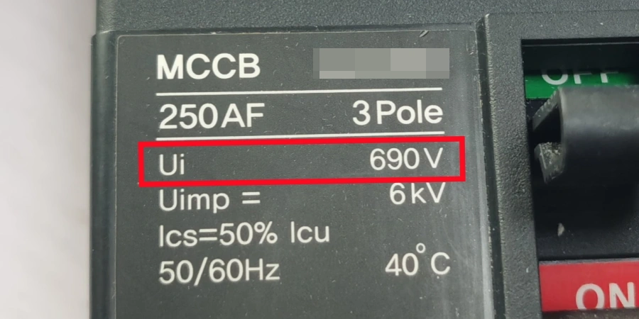
Light industrial or conventional distribution systems: In environments without heavy inductive loads or long cable runs, Ui = 690 V may still be used. It provides sufficient insulation performance while keeping cost lower.
-
Intermediate industrial applications (Ui = 800 V): Ui = 800 V is sometimes used as a middle step between 690 V and 1000 V. It appears in certain industrial switchgear designs where the system is not fully “heavy duty,” but still experiences more electrical stress than basic 690 V equipment. This can include compact distribution systems, mixed-load environments, or equipment designed to meet specific manufacturer or regional standards. It is less common than 690 V or 1000 V, but it exists as a practical compromise in some product lines.
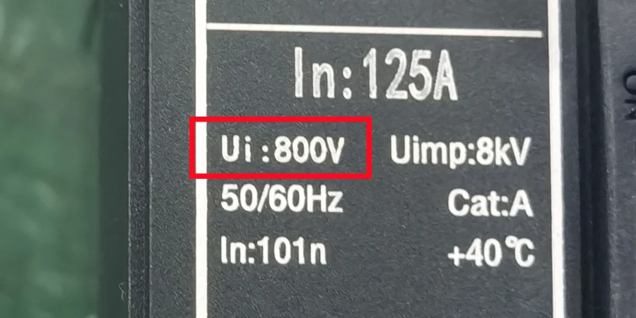
Ui 800V MCCB -
Low-stress control or auxiliary equipment: Some control panel components and auxiliary protection devices operate in relatively stable conditions, so they do not require the higher insulation margin of 1000 V.
In general, Ui selection is a balance between system complexity, overvoltage risk, and cost.
| System Voltage | Minimum Recommended Ui | Common Uimp |
|---|---|---|
| 230 V AC | 500 V | 6 kV |
| 400 / 415 V AC | 1000 V | 8 kV |
| 690 V AC | 1000 V | 8–12 kV |
From most manufacturer catalogs, you will see the same pattern: Ui is usually 1000 V for both 415 V and 690 V systems. This is because insulation requirements do not decrease much just because the nominal operating voltage is lower.
Another important point is that although lower Ui products still exist, their use in modern industrial systems is becoming less common. This is mainly because equipment like variable speed drives, UPS systems, and long cable runs introduce more frequent and more complex overvoltage conditions. As a result, engineers often prefer to standardize on 1000 V Ui to reduce design risk and simplify equipment selection.
The Reliability Connection
There is data that supports why this matters in practice. A reliability study on power circuit breakers covering failure records from 1989 to 2011 found that failures related to "live parts and insulation" accounted for roughly 52% of all breaker failures recorded. That is the largest failure category — higher than mechanical failures, larger than control circuit failures, larger than anything else.
In other words, insulation failure is not a secondary concern. It is the leading cause of circuit breaker failures in service. A properly chosen Ui, with sufficient margin above the operating voltage, directly targets the most common failure mechanism in these devices. And that is exactly what this rating is designed to do.
What Happens When Ui Is Too Low?
When people first hear about this topic, a natural question comes up: what actually happens if the Ui is too low? Does the breaker fail immediately, or is it just a theoretical concern that rarely shows up in real life?
In practice, the answer is less obvious. A breaker with an undersized Ui will usually not show any immediate problems. It can still operate normally in the early stage and appear fully compliant in everyday conditions. However, what is happening inside the insulation system is more subtle. The electrical stress is higher than what the design was intended for, and that stress starts to build up over time.
The Risk Is Not Always Immediate
This is what makes a low Ui particularly tricky. A breaker with Ui = 690 V installed in a 415 V system will not trip incorrectly or fail on the first day. It can run seemingly fine for months. However, every time the system experiences a switching surge, a temporary overvoltage, or a voltage spike from a nearby equipment, the insulation inside that breaker absorbs stress that it was not fully designed to handle.
Insulation damage is cumulative. Each event that pushes the system close to or beyond the insulation’s design limit leaves behind a small amount of degradation. Over time, this begins to show up in several specific failure modes.
Flashover
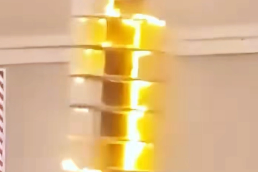
A flashover happens when voltage across an air gap or along an insulating surface exceeds the breakdown strength of that insulation path. Inside a circuit breaker, this can happen between poles, between live parts and the enclosure, or along a creepage paths on insulating components. Flashover during transient overvoltages is one of the most severe outcomes of insufficient insulation margin. When it happens, it typically results in a short circuit, major internal damage, and in some cases, complete device failure.
Partial Discharge and Surface Tracking
Partial discharge is a more subtle but equally damaging issue. It refers to small electrical discharges that occur within voids in insulation materials or along surfaces, without fully bridging the gap between conductors. Even though these discharges are small, they gradually erode insulation, create carbonized paths, and reduce overall insulation strength over time.
Surface tracking follows a similar mechanism. In environments with dust, humidity, or chemical contamination, conductive deposits on insulating surfaces can create paths for leakage current. If the insulation margin is already thin due to a low Ui, even modest surface contamination can become a serious issue. Insulation testing guidance shows that tracking damage on breaker insulation is often irreversible — once the conductive path forms, the only solution is replacement.
![]()
Accelerated Aging in Real Conditions
Laboratory testing conditions are controlled and stable, but real-world installations are not. Temperature cycling, humidity, vibration, and airborne pollutants all influence how insulation behaves over time. A breaker with a reduced insulation margin has less tolerance for all of these combined stresses.
When insulation is repeatedly exposed to stress levels near its limits, aging accelerates. A device that might have lasted 20 years under proper specification can fail significantly earlier when the insulation margin is insufficient and environmental conditions are even moderately harsh.
The Replacement Mistake
One of the most common real-world problems happens during replacement. An original breaker with Ui = 1000 V reaches end of life or trips or is damaged. A replacement is sourced quickly, often based on matching Ue and current rating. Ui gets overlooked.
The new breaker may work correctly electrically, so no one notices it. However, the insulation margin has now been reduced, even though the panel was originally designed around a 1000 V insulation reference level. The Victron Energy community discussion on circuit breaker voltage ratings touches on exactly this scenario — where matching only the operational voltage rating leads to an undersized insulation level in practice.
| Consequence | Cause | Visible Immediately? |
|---|---|---|
| Flashover | Voltage spike exceeds insulation limit | Sometimes — often causes trip or damage |
| Partial discharge | Repeated stress below breakdown threshold | No — damage is gradual and internal |
| Surface tracking | Leakage current along contaminated surfaces | No — develops over weeks or months |
| Accelerated aging | Repeated stress plus environmental factors | No — shows up as early failure in service |
Across all four cases, the pattern is the same: the effects of a low Ui are mostly invisible in the short term but accumulate silently over time. That is what makes it risky. In the long run, selecting the correct Ui from the beginning is almost always the more cost-effective and reliable choice.
Conclusion
Good design is not only about what works today, but what continues to work under stress. Ui reflects that thinking. It ensures the breaker is prepared for conditions that are not always visible or predictable, helping maintain performance and safety even as the system experiences real-world fluctuations over time.