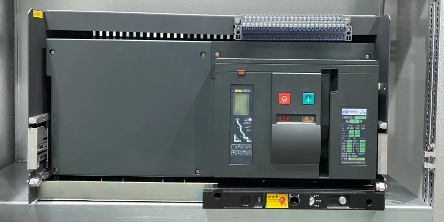
When we talk about ACBs, have you ever noticed that they usually show up in low-voltage systems, but you rarely see them in high-voltage setups? It’s a curious thing—why does the same kind of breaker behave so differently depending on the voltage?
From our experience supplying breakers, we’ve seen firsthand why higher voltages are trickier. The higher the voltage, the harder it is to control the electric arc, keep everything insulated, and make the breaker operate safely. A standard low-voltage ACB just isn’t built for those challenges.
The reasons go beyond the size of the frame or the current it can carry. When a fault happens, the arc, insulation, and how quickly the contacts open all start to matter in ways you might not expect. Understanding that helps explain why ACBs stick to low-voltage systems.
Typical Voltage and Current Ratings of ACBs
A while back, a customer asked if ACBs could be made for medium-voltage, like 3.3 kV, for some of their projects. Our engineering team immediately said no. The reasons behind that answer are more complicated than they seem.
Standard Voltage Ranges
Most ACB product lines you’ll see in catalogs are rated for 400 V, 690 V, or sometimes up to 1000 V AC systems. In our factory, we produce frames for 415 V applications (common in many Asian and Middle Eastern markets) and 690 V for industrial plants with higher distribution voltages. Some manufacturers push the envelope a bit—I’ve seen specialty units rated for 900 V—but these are still firmly in what the industry calls "low voltage."
The definition of low voltage itself varies slightly by region and standard. In IEC markets, low voltage generally means up to 1000 V AC or 1500 V DC. In North America, the NEC defines it a bit differently, but the practical result is similar: ACBs live below 1 kV, and anything above that enters medium-voltage land where vacuum and SF₆ breakers come into play.
Current Ratings and Frame Sizes
Here’s where ACBs really shine. Our product range starts at around 630 A and goes up to 6300 A in the largest frames. I remember when a mining project needed 5000 A continuous rating at 690 V—that’s the kind of application where ACBs are perfect. The breaker has to handle enormous steady-state current while still being able to interrupt fault currents that might reach 100 kA or more.
| Parameter | Typical ACB Range |
|---|---|
| Rated operational voltage | 400–690 V AC (some up to 1000 V) |
| Rated current | 630–6300 A (common frames) |
| Short-circuit breaking capacity | 25–150 kA (high-end up to 200 kA at LV) |
The breaking capacity is another critical spec. Customers sometimes focus only on the continuous current rating, but the breaking capacity might be even more important. A 3200 A ACB might have a breaking capacity of 100 kA at 415 V, meaning it can safely interrupt a fault current of 100,000 amperes. That’s a lot of energy to manage, and it requires precious engineering in the arc chutes, contact materials, and operating mechanisms.
Different projects have different needs. A commercial building might only need 65 kA breaking capacity, while an industrial plant close to a transformer substation might see prospective fault currents of 100 kA or higher. That’s why we offer the same frame size with different breaking capacity options—it keeps costs reasonable while meeting the actual system requirements. You don’t want to over-specify and waste money, but under-specifying could create a serious safety hazard.
Why Air Struggles with Higher Voltages?
Air circuit breakers perform reliably in low-voltage systems, but their limits become clear as voltage increases. The main challenge is not mechanical design—it is the physics of arc interruption. Once voltage rises into the medium-voltage range, controlling the arc in open air becomes significantly more difficult.
The Arc-Quenching Challenge
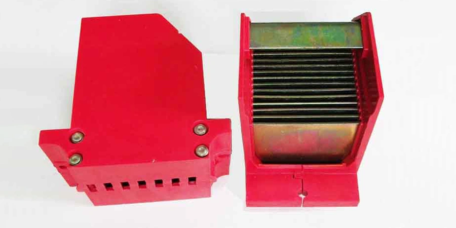
When an ACB’s contacts separate under fault conditions, an electric arc forms between them. This arc is essentially ionized air—a plasma path that continues to conduct current even though the contacts are physically apart. The arc chutes inside the breaker are designed to deal with this arc by breaking it into smaller pieces, cooling it, and stretching it until it extinguishes at a current zero (when the AC waveform crosses zero).
At 400 V or 690 V, this works well. Air has enough dielectric strength to support the arc-quenching process without requiring huge contact gaps or enormous arc chutes. But voltage and arc behavior don’t scale linearly. If you tried to interrupt a fault at 11 kV using the same air-based approach, the arc would be much longer, much hotter, and much harder to control. The contact gap would need to be significantly larger—maybe 5 or 10 times larger—just to prevent the arc from re-striking after interruption.
A 690 V arc might extend 50-100 mm in the arc chute, but an 11 kV arc could need several hundred millimeters of separation. That means the entire breaker gets bigger, heavier, and more complex. You’d need larger arc chutes with more splitter plates, stronger operating mechanisms to open the contacts faster and farther, and much better insulation throughout the entire structure.
Insulation and Clearance Requirements
Air’s dielectric strength at atmospheric pressure is roughly 3 kV/mm, but in practice, safety clearances inside switchgear need to be much more conservative. Standards require specific clearance and creepage distances based on system voltage, pollution levels, and altitude. At low voltage, these distances are manageable—maybe 10-20 mm between phases and to ground. At medium voltage, you’re talking about clearances measured in tens or hundreds of millimeters.
| Voltage Level | Typical Technology | Arc Medium | Contact Gap | Typical Size |
|---|---|---|---|---|
| Up to 1 kV | ACB | Air at atmospheric pressure | 50–150 mm | Large (draw-out frames) |
| 3.3–36 kV | VCB | Vacuum | 10–20 mm | Compact (sealed bottles) |
| Above 36 kV | SF₆ CB | SF₆ gas | Variable | Larger (gas-insulated) |
This is why the industry shifted to vacuum and SF₆ technologies for medium and high voltage. A vacuum interrupter can extinguish an arc in a sealed bottle with a contact gap of just 10-20 mm, even at 12 kV or 24 kV. The vacuum provides excellent dielectric strength, fast arc extinction, and long service life in a compact package. SF₆ gas does something similar at even higher voltages, though environmental concerns are pushing the industry toward new solutions.
When I explain this to customers, I sometimes use an analogy: trying to make an air circuit breaker work at 11 kV is like trying to use a residential fan to cool an industrial furnace. Sure, you could build a massive fan with huge blades and a powerful motor—but at some point, it makes more sense to use a different technology designed for that heat level. The same logic applies here. Air works great for low-voltage arc interruption, but beyond about 1 kV, you’re better off using vacuum or gas-insulated designs.
What’s Used Instead: Vacuum and SF₆ Breakers for Medium Voltage
ACBs work well in low-voltage systems, but they run into limits when the voltage gets higher. At medium voltage, air just can’t handle the arc safely and efficiently, so other types of breakers are needed.
The Vacuum Circuit Breaker Advantage
Vacuum circuit breakers(VCBs) completely changed medium-voltage distribution when they matured in the 1970s and 80s. Instead of interrupting an arc in open air, a VCB uses a sealed vacuum bottle—essentially a ceramic or glass cylinder with contacts inside and all the air pumped out. When the contacts separate under fault conditions, an arc still forms, but it behaves completely differently in vacuum than in air.
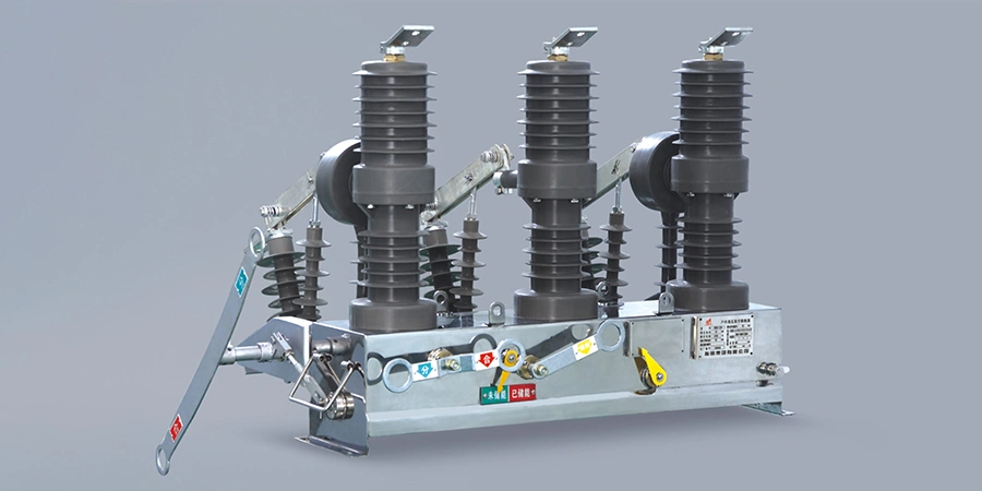
In vacuum, there’s no air to ionize and sustain the arc. The arc is composed of metal vapor from the contacts themselves, and it extinguishes extremely quickly—often within a half-cycle or less. This means the VCB can interrupt high fault currents with a much smaller contact gap.
The practical benefits are huge. Vacuum breakers are compact enough to fit in metal-clad switchgear that’s a fraction of the size of old air-insulated switchgear. They require virtually no maintenance—the vacuum bottle is sealed for life, typically rated for 10,000 to 30,000 mechanical operations. Compare that to an air breaker, where you need to inspect and clean the arc chutes, check contact wear, and maintain the operating mechanism regularly.
Most modern VCB applications fall in the 3.3 kV to 36 kV range. I’ve seen product lines that go down to 1.14 kV for special applications, but the sweet spot is really 11 kV to 33 kV where the majority of industrial and utility distribution happens. A typical 12 kV vacuum breaker might be rated for 630 A to 2000 A continuous current with breaking capacities of 25 kA to 40 kA—plenty for most medium-voltage feeders.
SF₆ Technology and Environmental Considerations
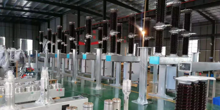
Above 36 kV, SF₆ (sulfur hexafluoride) gas circuit breakers become more common, especially in transmission substations. SF₆ is an excellent insulating and arc-quenching gas—much better than air. It can handle very high voltages in relatively compact enclosures, which is why you see it in 132 kV, 220 kV, and even higher voltage systems.
However, SF₆ has a major downside: it’s an extremely potent greenhouse gas. Some regions are starting to restrict or ban new SF₆ equipment. The industry is exploring alternatives—gas mixtures, vacuum technology pushed to higher voltages, or clean air technology—but for now, SF₆ is still standard at transmission levels. For most industrial and commercial projects in the medium-voltage range, though, vacuum technology is the go-to choice.
Why the Industry Shifted Away from Air at Medium Voltage?
People sometimes ask me why older plants still have air-magnetic breakers or air blast breakers at medium voltage if air is so problematic. The answer is simple: those breakers were installed 30, 40, or even 50 years ago, before vacuum technology became reliable and affordable. Back then, air was the best available option for medium voltage.
I’ve toured industrial plants that still run on vintage air-insulated medium-voltage switchgear from the 1970s. These installations are massive—entire rooms dedicated to switchgear that today could now fit in a couple of metal-clad cabinets. The breakers themselves are enormous, with complex pneumatic or spring operating mechanisms, large arc chutes, and extensive buswork requiring significant clearances. Maintenance is labor-intensive and parts are getting hard to find.
When these facilities finally upgrade or retrofit, they almost always switch to vacuum breakers. The difference is night and day. The new switchgear is smaller, safer, more reliable, and easier to maintain. The old air breakers might have needed quarterly inspections and annual maintenance; the vacuum replacements might go five or ten years between service intervals. That’s a huge operational advantage, especially when you consider labor costs and downtime.
Conclusion
Not every electrical problem needs a bigger version of the same solution. Sometimes it requires a different approach altogether. Knowing where air circuit breakers fit—and where they don’t—can save time, reduce risk, and lead to more reliable power systems.