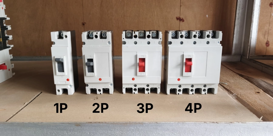
When you open a circuit breaker catalog, you might notice something curious: ACBs almost never come in 1-pole or 2-pole versions, while other breakers, like MCBs or MCCBs, are available from 1 to 4 poles. Have you ever wondered why?
When we talk with our customers, this question often comes up from new buyers. Many assume that pole selection is just a design choice or a matter of cost, but in reality, it’s closely tied to how three-phase electrical systems operate.
Once you understand how current flows in a three-phase system, it becomes clear that the standardization on 3-pole and 4-pole breakers isn’t random. Behind it lies safety, efficiency, and easier maintenance—which is why nearly all industrial and commercial power distribution relies on these two configurations.
Understanding Poles in Circuit Breakers: 3P vs 4P
When we talk about poles in a circuit breaker, we’re referring to the number of separate current-carrying paths that the device can simultaneously switch and protect.
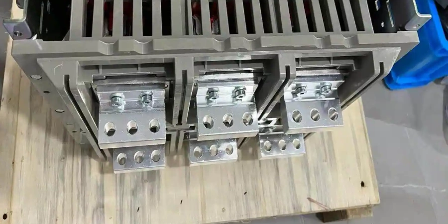
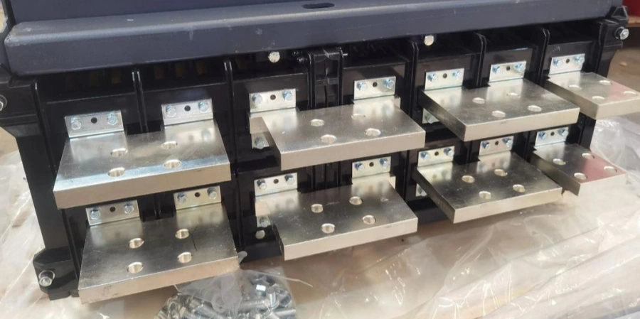
Think of each pole as an independent switching unit with its own contacts, arc chutes, and trip mechanism, all mechanically linked to operate together. A 3-pole ACB has three such units, one for each phase conductor in a three-phase system: L1, L2, and L3. A 4-pole ACB adds a fourth unit specifically for the neutral conductor.
The Anatomy of Each Pole
Here’s what’s happening inside these poles, based on what I’ve observed on the production line. Each pole contains a fixed contact and a movable contact. When the breaker is closed (conducting), these contacts press together with significant force—we’re talking hundreds of pounds of contact pressure in larger frames—to ensure a low-resistance connection that won’t overheat during normal operation.
When the breaker trips or is manually opened, a powerful spring mechanism drives the movable contacts apart. The speed of this separation is critical. Too slow, and the arc that forms will have time to damage the contacts or even prevent the circuit from opening. I’ve seen high-speed camera footage of this process—at thousands of frames per second, the contacts separate so fast it’s just a blur.
In a 3-pole breaker, this contact opening happens simultaneously across all three phase poles. The mechanical linkage ensures that you can’t have L1 open while L2 and L3 remain closed—it’s all or nothing. This simultaneity is crucial for motor protection and system safety. A motor fed by only two phases instead of three will draw excessive current while starting, potentially destroying the motor windings.
What Makes the 4th Pole Different?
That fourth pole in a 4-pole breaker is for the neutral conductor, but it’s not always exactly like the other three poles. During one team meeting, I learned that manufacturers actually offer different neutral pole configurations depending on the system requirements.
-
Fully rated neutral pole: The neutral contacts, arc chutes, and current-carrying capacity are identical to the phase poles. This is necessary when the neutral is expected to carry the same current as the phases, which is common in systems with many single-phase loads or nonlinear equipment.
-
Reduced-rated neutral pole: The contacts and interrupting capability are still present but sized for a lower continuous current. This works in balanced three-phase systems, where the neutral normally carries very little current. The neutral is switched for isolation purposes but doesn’t need the same thermal capacity as the phase poles.
-
Switched-only neutral: The neutral pole opens and closes with the phases but has no independent trip unit. If excessive neutral current flows, the ground fault or phase overcurrent protection triggers a trip, opening all four poles together. This configuration is mainly for isolation, not individual neutral protection.
The Mechanical Linkage Challenge
Manufacturing 4-pole ACBs is trickier than it sounds. All four poles must operate in proper sequence. In most cases, you want all four poles—three phases plus neutral—to open at the same time. But in some specific installations, customers need what’s called an "early-make, late-break" neutral.
I once watched our technical team implement this for a generator application. The neutral needed to close slightly before the phase poles and open slightly after them. This timing helps prevent sudden voltage spikes and keeps the grounding correct during switching.
Achieving this with mechanical linkages, while maintaining the speed and reliability required for fault interruption, is really impressive engineering. The tolerances are tight—we’re talking about milliseconds of difference in operation across poles that are being driven by the same mechanism.
| Configuration | Neutral Pole Rating | Protection | Typical Application |
|---|---|---|---|
| 3-Pole | None | Phase overcurrent only | Balanced three-phase loads, no neutral |
| 4-Pole (Full-rated) | Same as phase poles | Individual neutral protection | Heavy single-phase loads, harmonic currents |
| 4-Pole (Reduced) | Lower than phase poles | Neutral switched, limited protection | Light neutral current, isolation required |
| 4-Pole (Switched only) | No overcurrent protection | Ground fault triggers trip | Isolation without independent neutral trip |
Real-World Current Flow in Three-Phase Systems
Understanding 3-pole vs 4-pole really comes down to how current flows in three-phase systems. In a perfectly balanced three-phase system—say, three identical heaters each connected between a phase and neutral—the currents in each phase are equal in magnitude but shifted 120 degrees in time. Add them together vectorially, and the sum is zero. In this ideal case, the neutral carries no current, so you don’t need to switch or protect it.
But ideal conditions are rare. Single-phase loads naturally unbalance the system. For example, if L1 carries 100A of lighting, L2 50A of receptacles, and L3 75A of equipment, the neutral carries the difference—the vector sum of unbalanced currents.
Modern nonlinear loads make this issue even more critical. Devices like variable frequency drives, switching power supplies, LED lighting, computers, and UPS systems draw nonsinusoidal currents. Certain harmonics—particularly multiples of the third harmonic—add in the neutral instead of canceling out.
I’ve seen cases neutral currents can exceed the phase currents due to harmonics. In these situations, a 4-pole ACB isn’t just recommended—it’s essential. Running high current through an unprotected neutral is a fire hazard waiting to happen.
Why ACBs Are Limited to 3P and 4P?
Theoretically, people could make a 2-pole ACB—there’s no physical law preventing it. But the real answer is far more interesting and rooted in the fundamental nature of electrical distribution systems.
The power distribution infrastructure worldwide is built around three-phase systems. Whether you’re in North America, Europe, Asia, or anywhere with industrial electrical infrastructure, the backbone is three-phase power generation, transmission, and distribution.
This isn’t arbitrary—three-phase power is the most efficient way to generate, transmit, and use electrical energy at scale. It provides constant power delivery (unlike single-phase which pulses), more efficient use of conductor materials, and the ability to create rotating magnetic fields for motors without additional components.
The Distribution System Reality
When I started in this factory, I thought our product lineup was driven mainly by what we could manufacture. I quickly learned it’s the opposite—we manufacture what the electrical distribution infrastructure actually needs. Walk into any industrial facility, commercial building, or utility substation, and you’ll find that the main power feeders are either three-phase three-wire systems (no neutral) or three-phase four-wire systems (with neutral). That’s it. Those are the two configurations that dominate low-voltage distribution.
Three-phase three-wire systems are common for purely industrial loads: large motors, industrial machinery, three-phase heating elements, and equipment that doesn’t need a neutral reference. The electrical service comes in as L1, L2, L3, and ground. A 3-pole ACB protecting this service switches all three phases simultaneously, providing complete isolation when needed.
Three-phase four-wire systems add the neutral conductor, creating what you’ll find in mixed-use facilities: commercial buildings with three-phase HVAC equipment and single-phase lighting, industrial plants with both motors and control systems, or anywhere you need both three-phase and single-phase loads from the same service. Here, a 4-pole ACB switches L1, L2, L3, and neutral together.
But where’s the demand for 1-pole or 2-pole ACBs? Single-phase circuits certainly exist—lots of them—but they’re downstream from the main distribution. They’re the branch circuits, the final loads, the individual pieces of equipment. These circuits are already well-served by MCBs and MCCBs, which are smaller, less expensive, and perfectly enough for single-phase applications up to several hundred amperes.
The Economics of Standardization
One lesson I picked up from meetings is that every new product variation adds complexity across the entire organization. New tooling, different parts inventory, different documentation, different testing procedures, different certification requirements. That cost only makes sense when there’s enough demand to justify it.
Our production data shows that 3-pole and 4-pole ACBs account for well over 95% of all ACB installations worldwide. The remaining 5% of cases where someone might think they need a different pole count can almost always be solved with existing products—either a standard 3-pole or 4-pole ACB for larger circuits, or an MCCB for smaller ones.
Standard options usually mean simpler installation, better parts availability, easier maintenance, and faster replacement when needed. Standardization isn’t just about manufacturing efficiency—it supports a more reliable and practical system overall.
Design Standards and Safety Requirements
International standards also play a major role. ACBs are designed and tested under frameworks like IEC 60947-2 for low-voltage switchgear and IEC 60364 for electrical installations. When you look at the test procedures, performance requirements, and safety specifications, they assume you’re dealing with three-phase systems.
In our testing lab, every new ACB design goes through extensive type testing: making and breaking capacity tests, short-circuit performance, temperature rise, mechanical endurance, electrical endurance, and more. All of these tests assume 3-pole or 4-pole operation because that’s what the standards—and real-world installations—are built around.
Adding a non-standard pole configuration would mean developing new test procedures, obtaining separate certifications, and convincing standards bodies and regulatory agencies that the product meets safety requirements. For a product that might sell a few dozen units each year, the effort simply doesn’t make sense.
The Switchboard Integration Factor
Something that became obvious once you visit customer sites is that ACBs don’t exist on their own—they’re part of a larger switchboard system that includes busbars, protection devices, metering, and control. The entire ecosystem is designed around 3-pole and 4-pole configurations.
Busbar systems in low-voltage switchgear come with three or four horizontal or vertical bars (three phases plus optional neutral), with connection points spaced for standard ACB footprints. Panel builders stock the cable lugs, insulation barriers, and mounting hardware for 3-pole and 4-pole units. Electrical designers create standard panel layouts that accommodate these configurations efficiently.
Even if we built a 2-pole ACB, integrating it into an existing switchboard would likely be more complicated and more expensive than using a standard unit.
| System Type | Conductors | Typical ACB Configuration | Why This Configuration |
|---|---|---|---|
| Three-phase three-wire | L1, L2, L3 + Ground | 3-Pole | No neutral to switch; all active conductors protected |
| Three-phase four-wire (balanced) | L1, L2, L3, N + Ground | 3-Pole or 4-Pole | Neutral switched only if isolation is needed |
| Three-phase four-wire (unbalanced) | L1, L2, L3, N + Ground | 4-Pole | Neutral carries current and must be switched |
| Single-phase circuits | L, N + Ground | MCB or MCCB | ACB not appropriate for this application |
The MCCB Overlap Zone
There’s an interesting overlap between MCCBs and ACBs in roughly the 100A to 800A range. Since we manufacture both, some beginners often ask which one to choose in the real project. The answer usually comes down to application needs rather than current rating alone.
MCCBs are available in 1-pole, 2-pole, 3-pole, and 4-pole versions. They cover the single-phase and small three-phase applications beautifully. They’re compact, less expensive, and often easier to install than ACBs. For a 400A single-phase circuit, an MCCB is almost always the right choice.
ACBs come into play when you need features that MCCBs can’t provide: draw-out construction for easy maintenance, advanced protection and metering capabilities, higher breaking capacities, or compliance with specific switchgear standards. These features make sense primarily at the main distribution—which, again, is three-phase territory.
That’s why ACBs naturally standardize on 3-pole and 4-pole designs. The applications that justify using an ACB instead of an MCCB are overwhelmingly three-phase. It’s a self-reinforcing cycle: ACBs are designed for three-phase systems, so they’re specified for three-phase installations, which confirms that those are the configurations the market actually needs.
Final Thoughts
In the end, pole count isn’t about adding features for their own sake. It’s about matching the breaker to how power is actually used, maintained, and protected over time. Choosing what’s standard often leads to fewer surprises long after first use.