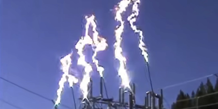
Electric arcs are the enemies of circuit breakers. They appear the instant current tries to jump across separating contacts, threatening equipment, safety, and even entire power systems. Left uncontrolled, these arcs can cause serious damage, downtime, or hazards for operators.
Because of these risks, controlling arcs has always been a central challenge for engineers. It requires understanding how electricity, heat, and materials interact under extreme conditions. Every innovation in this field reflects careful problem-solving and creativity, aiming to make systems safer, faster, and more reliable.
Looking closer at how arcs are managed reveals a bigger lesson. Even small, invisible forces can have huge consequences, and the solutions we develop shape the safety and efficiency of the power systems we depend on every day—often without ever noticing.
Vacuum Arc Suppression
I remember my first time seeing vacuum breaker in a factory back in 2017. At the time, I was skeptical—how could something that seemed to have “nothing inside” work better than traditional systems? But seeing it in action completely changed my mind. The lack of any gas or liquid medium created the ideal conditions for rapid arc extinction.
The Science Behind the Speed
The idea behind vacuum arc suppression is simple: remove the fuel, and the fire dies. When the contacts pull apart in a vacuum chamber, an electrical arc forms as a plasma column between them. In normal air, this plasma would be sustained by ionizable molecules. In a near-perfect vacuum, there’s nothing to keep the ionization alive.
Here’s where the physics get interesting. At first, the arc vaporizes a small amount of metal from the contact surfaces, creating a temporary conductive path. But without surrounding gas to support the plasma state, that vapor quickly cools, condenses, and disperses. The whole sequence wraps up in less than 10 milliseconds—quicker than the blink of an eye.
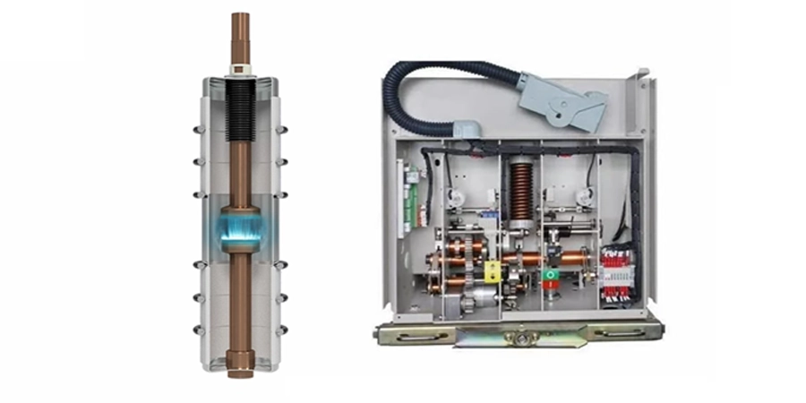
This speed is only part of the appeal. Vacuum breakers are consistent. Unlike gas-blast systems that depend on pressure changes, or oil-based systems that rely on chemical reactions, vacuum breakers behave the same way every time. The vacuum itself doesn’t wear out, doesn’t need refilling, and keeps its properties stable across different temperatures.
Market Performance and Reliability
These technical advantages show up clearly in the market. Analysts estimate the global vacuum breaker market at USD 5.9 billion in 2024, with an expected annual growth rate of 7.9% through 2034. That growth isn’t just speculation—it reflects the real-world benefits that managers see.
Vacuum breakers are also easy to maintain. Many operators have told me their systems have run reliably for over ten years, needing nothing more than the occasional check on the contacts. Because the chambers are sealed, they don’t collect dust or moisture, don’t leak gas, and don’t need fluid replacement. Over the lifespan of the equipment, that adds up to substantial savings.
And when reliability is the top priority, vacuum breakers deliver unmatched performance. Facilities like data centers, hospitals, and high-volume manufacturing plants simply cannot risk breaker failures. In these mission-critical settings, vacuum technology has built a reputation for dependable performance.
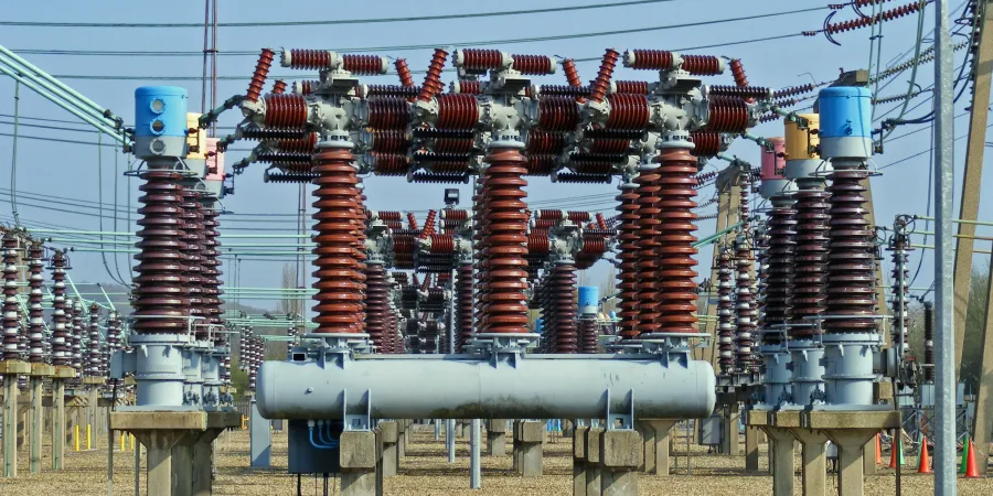
SF₆ Gas-Blast Quenching
Sulfur hexafluoride (SF₆) is one of the most effective arc-quenching mediums ever developed. But its effectiveness comes with a heavy environmental cost—one that often leaves me conflicted.
While working with utility companies upgrading their high-voltage infrastructure, I’ve seen how SF₆’s technical advantages force engineers to weigh raw performance against environmental responsibility.
Superior Dielectric Performance
SF₆ gas-blast breakers operate by injecting high-pressure SF₆ directly into the arc chamber during interruption. This achieves two critical goals at once: the gas soaks up the enormous heat energy from the arc plasma, and it creates a strong insulating barrier to stop the arc from reigniting.
The cooling process works at the molecular level. When the hot plasma collides with SF₆ molecules, they absorb heat through their vibrational and rotational energy states, pulling energy out of the arc. At the same time, SF₆’s high electronegativity makes it a powerful insulator, preventing current from reforming once it drops to zero. This unique combination makes SF₆ the go-to choice for high-voltage applications above 72 kV, where other quenching methods can’t keep up.
Another strength of SF₆ systems is their compactness. Air-blast breakers need bulky compressors and piping to deliver comparable performance, while SF₆ equipment achieves the same interrupting capacity in a much smaller package. This space efficiency becomes especially valuable in urban substations, where every square meter carries a premium price.

Environmental Challenges and Innovation
Of course, the story doesn’t end with performance. SF₆ also happens to be one of the most potent greenhouse gases ever identified, with a global warming potential about 25,000 times that of CO₂. Whenever I share this with environmentally conscious friends, their enthusiasm for SF₆’s technical brilliance tends to fade quickly.
The power industry is well aware of this dilemma, and significant research is underway to find safer alternatives. Engineers are experimenting with compressed air, synthetic blends, and other gases. So far, though, none have matched SF₆’s unique mix of cooling capacity, dielectric strength, and compactness. To bridge the gap, many newer systems now include SF₆ recovery units, which capture and recycle the gas during maintenance to minimize emissions.
| SF₆ Characteristics | Performance Rating | Environmental Impact |
|---|---|---|
| Dielectric Strength | Excellent | Very High GWP |
| Arc Cooling Capacity | Superior | Long Atmospheric Lifetime |
| System Compactness | Very Good | Requires Specialized Handling |
| Maintenance Requirements | Moderate | Gas Recovery Systems Needed |
Looking ahead, regulations around SF₆ are becoming stricter. Some regions have already set phase-out timelines for new installations, creating pressure to find replacements. But the challenge remains: how do you retire such an effective technology without sacrificing reliability in critical high-voltage systems?
Air-Blast Arc Extinction
Air-blast breakers are the environmentally conscious option in the circuit breaker world—safe, clean, and relying on a resource that’s both abundant and free. I’ve always admired their simplicity: use high-velocity compressed air to physically blow the arc apart while cooling the contact area.
Mechanical Simplicity Meets Physical Effectiveness
Compared to vacuum or SF₆ systems, air-blast breakers operate on almost intuitive principles. High-pressure air, stored in tanks at 200–300 psi, is released through carefully engineered nozzles aimed directly at the arc. The blast performs three key functions: it pushes ionized particles away from the contact zone, cools the area through convective heat transfer, and introduces neutral air molecules that help deionize the arc path.
The timing in these systems is critical. The air must be released precisely as the contacts separate—too early, and the air is wasted; too late, and the arc can already cause damage. Modern designs rely on advanced valves and electronic controls to maintain this precision consistently.
Air-blast breakers work especially well in medium-voltage applications. Industrial plants, commercial buildings, and distribution networks often favor them because the voltage levels don’t require the extreme interruption performance of high-voltage SF₆ systems, and the environmental benefits are clear.
Infrastructure Requirements and Performance Trade-offs
The biggest challenge with air-blast systems isn’t the technology itself – it’s the supporting infrastructure required. These systems need substantial air compressors, pressure tanks, filtration equipment, and distribution piping. I’ve toured substations where the air handling equipment occupies more space than the breakers themselves.
Keeping air-blast systems running smoothly requires more maintenance than vacuum or SF₆ systems. Air compressors need regular service, filters require replacement, and moisture control is critical to prevent ice formation in cold climates. The compressed air must be exceptionally clean and dry, because any contamination can affect arc extinction performance or cause corrosion in the breaker mechanisms.
Performance is another trade-off. Air-blast breakers typically operate slower than vacuum or SF₆ systems. While a vacuum breaker may interrupt a fault in about 10 milliseconds, air-blast systems often require 50–100 milliseconds. In power system protection, every millisecond counts, so this difference can influence equipment stress and overall system stability.
Operational costs are another factor. Compressing large volumes of air continuously consumes energy, which can noticeably increase electricity bills for big installations. Still, many facilities see this as an acceptable trade-off for avoiding the environmental and regulatory challenges associated with SF₆.
Grid (Arc Chute) Suppression
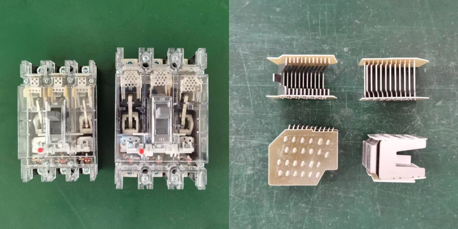
Arc chutes might look like simple metal grids, but they’re a brilliant example of clever engineering in low-voltage applications.
Every time I open a molded-case breaker for inspection, I’m reminded how this “divide and conquer” approach to arc control has become the backbone of building electrical systems worldwide.
Splitting the Arc for Better Control
Arc chute technology works by breaking a single dangerous arc into multiple smaller, more manageable arcs. The system uses a series of parallel metal plates or grids near the breaker contacts. When an arc forms during interruption, magnetic forces push it upward into these plates, creating several shorter arc segments.
Each individual arc segment behaves differently than the original single arc. Shorter arcs have higher voltage gradients per unit length, meaning they require more energy to maintain themselves. The multiple contact points with the metal plates provide additional cooling surfaces, rapidly extracting heat from the plasma. Most importantly, the sum of voltages across all these smaller arcs quickly exceeds the system voltage, causing the entire arc chain to collapse.
Designing arc chutes requires careful attention to plate spacing, materials, and magnetic field shaping. Plates placed too close together prevent proper arc formation, while plates too far apart reduce the splitting effect. Materials like steel or other magnetic metals help guide the arc using the magnetic forces generated by the fault current itself.
Cost-Effective Solution for Building Applications
Arc chutes have become the standard in molded-case and miniature circuit breakers because they deliver reliable performance at minimal cost. Unlike vacuum or SF₆ systems, manufacturing arc chutes only requires basic metalworking skills, making them accessible for residential, commercial, and light industrial use.
Maintenance is straightforward. Arc chutes don’t need gas refills, vacuum pumps, or specialized diagnostic tools. Often, a simple visual inspection is enough to spot when the plates need replacement. The plates themselves are passive, with no moving parts beyond the thermal effects of arc exposure.
Their main limitation shows up in higher-power applications. While perfect for typical building loads—lighting, receptacles, small motors—arc chutes struggle to handle the massive fault currents found in industrial or utility settings.
Even in this mature segment, the technology continues evolving. Modern arc chutes use improved materials, optimized geometries, and better integration with electronic trip units, extending their range and boosting performance consistency.
For manufacturers and assemblers, the quality of these internal components determines the final product’s reliability. Precision-stamped arc chutes are crucial for consistent breaking performance.
Magnetic Arc Blowout
The first time I saw a magnetic blowout system in action during a DC motor control demonstration, I immediately understood why this technology has such a strong following in specialized applications.
Unlike other arc suppression methods that rely on cooling or gas media, magnetic systems use pure electromagnetic force to physically stretch and extinguish the arc.
Electromagnetic Forces in Arc Control
Magnetic arc blowout systems position a coil or permanent magnets around the contact assembly to create a transverse magnetic field. When fault current flows through this field, the Lorentz force pushes the arc perpendicular to both the current and magnetic field lines. This elongates the arc, stretching it across a greater distance and into regions designed for optimal cooling.
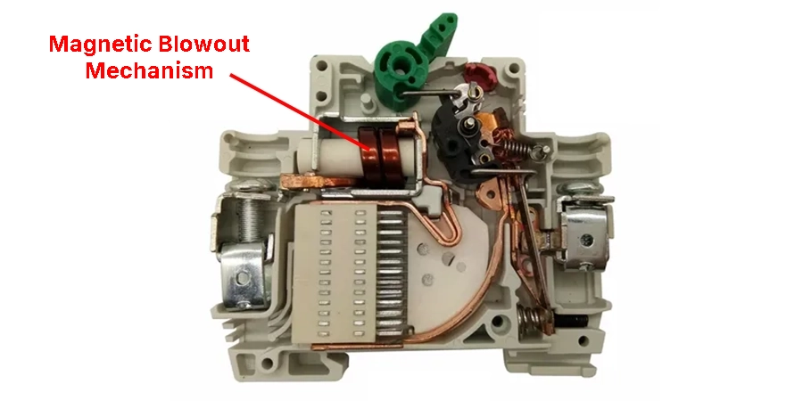
What fascinates me about this method is how visible the physics are. You can watch the arc bend and stretch as the magnetic forces take effect. The elongated arc experiences higher resistance due to its greater length and smaller cross-sectional area—a phenomenon engineers call the “thermal pinch effect.” As the arc thins, its resistance rises exponentially, demanding more voltage to sustain it until it finally collapses.
Magnetic systems are also self-reinforcing. Higher fault currents generate stronger magnetic forces, which automatically produce greater arc-stretching effects exactly when they are needed most. This scaling happens naturally across a wide range of fault conditions without the need for complex control algorithms.
DC Applications and Specialized Uses
DC circuits pose unique challenges that make magnetic blowout systems especially valuable. Unlike AC, where current naturally crosses zero twice per cycle, DC maintains constant polarity, giving arcs unlimited time to form stable plasma columns. DC motor drives where conventional breakers simply couldn’t handle these sustained arcs.
Magnetic blowout breakers actively fight arc formation from the moment contacts begin separating. The continuous magnetic force keeps the arc moving and stretching, preventing the stable plasma that makes DC interruption so difficult.
Marine systems are another ideal application. Ships often rely on DC for critical services, and the compact, self-contained nature of magnetic blowout breakers fits well with tight space constraints. The absence of compressed gases or vacuum chambers also reduces potential leak paths that could compromise watertight integrity.
Railroad traction systems have historically relied on magnetic blowout technology. Locomotives face harsh vibration, wide temperature ranges, and heavy-duty loads, requiring simple, robust solutions without auxiliary systems that could fail in operation.
| Magnetic Blowout Applications | Current Type | Key Advantages | Typical Industries |
|---|---|---|---|
| DC Motor Control | DC | Self-scaling force | Mining, Manufacturing |
| Marine Systems | DC/AC | Compact design | Shipping, Naval |
| Traction Control | DC | Vibration resistant | Railroad, Transit |
| Welding Equipment | DC | High-current handling | Metal fabrication |
Oil Immersion Quenching
Oil-filled circuit breakers carry a certain nostalgic significance in the industry—they were the foundational technology that enabled modern power systems, even though today they are often seen as relics of a past era.
While they played a crucial role in shaping today’s electrical infrastructure, their limitations make them less practical for modern applications.
Traditional Arc Extinction Through Oil Decomposition
Oil immersion breakers rely on transformer oil’s dual role as both an insulating medium and an arc-quenching agent. When contacts separate under oil, the intense heat of the electrical arc vaporizes surrounding oil molecules, generating hydrogen and other gases. These gases expand rapidly, forming turbulent flows that help blow the arc away from the contact surfaces.
The chemistry involved is complex. Arc temperatures can exceed 20,000°C, breaking down hydrocarbons into hydrogen, methane, acetylene, and carbon compounds. Hydrogen, being extremely light, rises quickly and generates strong convective currents. The expanding gas bubble also produces pressure waves that disperse ionized particles and cool the arc channel.
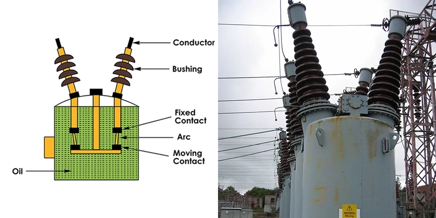
What made oil breakers attractive was their simplicity and effectiveness at high voltages. The oil provides excellent insulation between phases and to ground, enabling compact designs compared to air-insulated alternatives. For decades, transmission substations worldwide relied on oil technology because nothing else could consistently interrupt the massive fault currents at those voltage levels.
Environmental and Safety Concerns
The decline of oil breakers is largely due to environmental and safety concerns. Fire risk is the most immediate worry—oil breakers contain hundreds of gallons of flammable liquid under pressure, creating the potential for catastrophic failures.
Environmental regulations have also tightened significantly around oil handling and disposal. Used transformer oil often contains PCBs or other regulated compounds, requiring specialized disposal procedures. Regular oil testing, containment systems, and spill response capabilities add operational complexity that many facilities prefer to avoid.
Maintenance for oil systems requires expertise that is increasingly scarce. Oil analysis, degassing equipment, and contamination prevention require skilled technicians with specific training. As experienced specialists retire, finding qualified replacements becomes more difficult and costly.
Legacy Applications and Modern Standards
Despite these drawbacks, oil breakers are still used in niche applications where their characteristics remain advantageous.
Very high-voltage installations—especially above 500 kV—sometimes continue to prefer oil technology for its proven reliability and superior dielectric properties. Certain critical locations maintain oil breakers because their track record outweighs environmental concerns.
Modern safety standards reduce some of the risks. Facilities using oil breakers often install fire detection systems, deluge sprinklers, secondary containment, and oil-water separation equipment to comply with contemporary regulations.
Whether oil breakers can meet current safety and environmental standards depends heavily on the site and local regulations. While technically possible, the cost and complexity of upgrading often make replacement with modern alternatives the more practical choice.
Artificial Current-Zero Methods
Among all the arc extinction techniques I’ve learnt, artificial current-zero methods are perhaps the most intellectually sophisticated.
Rather than relying on natural phenomena, these systems create their own favorable conditions for arc extinction, showcasing remarkable engineering creativity—especially in solving the DC interruption challenge.
Creating Favorable Interruption Conditions
Artificial current-zero techniques work by temporarily forcing the main circuit current to zero. They do this by superimposing an auxiliary current that opposes the main flow. Arc extinction becomes much easier when current crosses zero—a condition that occurs naturally in AC systems but never appears in DC circuits.
Implementation typically involves a capacitor charged to system voltage but with opposite polarity. When interruption is required, switching circuits connect the capacitor across the main current path through a carefully tuned inductor. This creates an LC oscillation that temporarily drives the net current to zero.
During this artificial zero crossing, the arc loses its sustaining energy and begins to deionize. The system must then maintain enough dielectric strength to prevent the arc from reestablishing once the auxiliary pulse ends. Often, these methods are combined with other extinction techniques, such as gas blasts or vacuum chambers, to ensure reliable interruption.
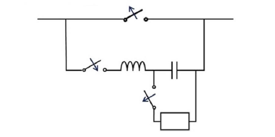
The engineering challenge lies in sizing the components correctly. The capacitor must store enough energy to bring the main current to zero, while the inductor controls the oscillation frequency for sufficient zero-crossing duration. Too small, and the current doesn’t reach zero; too large, and the system becomes bulky and expensive.
DC Circuit Protection and Specialized Applications
DC power systems highlight the value of artificial current-zero methods. Solar installations, EV charging infrastructure, and data center power systems increasingly use DC distribution for efficiency. Yet protective devices must overcome the absence of natural current zeros.
Battery storage systems are a growing area for this technology. Fault currents in these systems can be limited only by internal resistance, producing sustained arcs that conventional breakers struggle to interrupt. Artificial current-zero techniques reliably interrupt these arcs regardless of the DC source characteristics.
High-voltage DC (HVDC) transmission lines use advanced versions of artificial current-zero methods combined with other techniques. These systems handle currents of thousands of amperes at voltages exceeding 100 kV, pushing every available technology to its limits.
| Current-Zero Method Comparison | Natural AC Zero | Artificial DC Zero | Performance Impact |
|---|---|---|---|
| Zero Crossing Frequency | 120 times/second | On-demand | Immediate response capability |
| Current Interruption | Automatic | Controlled timing | Precise interruption control |
| System Complexity | Simple | Sophisticated | Higher initial cost |
| Reliability | Voltage dependent | System designed | Predictable performance |
As DC systems grow, artificial current-zero methods are becoming increasingly important. Advances in power electronics and energy storage are making the auxiliary components more compact and cost-effective, broadening the practical applications of this technology.
Conclusion
As power systems evolve, arc suppression isn’t just about breaking circuits efficiently—it’s a window into engineering trade-offs, environmental responsibility, and innovation. How we balance performance, safety, and sustainability today will shape the reliability and impact of tomorrow’s electrical infrastructure.
Turning these scientific principles into reliable products requires manufacturing expertise. If you are looking for a partner who understands the engineering behind every breaker, we are ready to assist.