As someone who used to panic when a light fixture stopped working, I never thought I’d be writing about electrical formulas. But after talking to dozens of electricians, I learned you don’t have to be a pro to understand the basics that keep your home safe and running.
These simple formulas are the same ones electricians use every day, boiled down to what matters most for homeowners. I’ve even tested them while upgrading my own home’s electrical system.
What surprised me most? They’re not complicated. With just basic math, you can stop guessing your home’s electrical needs and start making smart choices. Here are the essentials that finally helped me see what’s really going on behind my walls.
Ohm’s Law
Ohm’s Law might sound like something from a physics textbook, but it’s actually the foundation of everything electricians do.
It says that the current (I) flowing through a wire depends on the voltage (V) across it and the resistance (R) it offers. The formula is simple:
V = I \times RThis law is super useful because if you know any two of these values, you can easily find the third. This is key when you’re designing or fixing circuits.
A Real-World Example
Let me tell you about a time when Ohm’s Law saved the day. My friend was helping out on a control panel installation when one circuit just wouldn’t work. The voltage was there, but no current was flowing.
The electrician checked everything and then used a multimeter to test resistance. It was extremely high, which meant there was a break somewhere—a broken wire causing an open circuit. Thanks to Ohm’s Law, he quickly found the problem and fixed it without wasting time.
Why Ohm’s Law Is So Useful
Ohm’s Law is incredibly versatile. You can rearrange it to solve for current (I = \frac{V}{R}) or resistance (R = \frac{V}{I}). That flexibility makes it indispensable.
For example, if you’re installing a new light fixture rated at 120V with a resistance of 144Ω, you can calculate the current: I = \frac{V}{R} = \frac{120}{144} \approx 0.833\,A. Now you know exactly how much current that fixture will draw, so you can make sure your circuit can handle it without tripping breakers.
Knowing this helps make sure your circuit can handle the load without tripping breakers.
Series and Parallel Circuits
Ohm’s Law isn’t just for single resistors—it’s key to understanding how circuits work when you connect components in series or parallel.
Series Circuits
In a series circuit, all components are connected one after another, forming a single path for the current. This means:
-
Current is the same everywhere — the same current flows through each resistor or device.
-
Resistances add up — the total resistance is the sum of each individual resistance:
- Because total resistance increases, the overall current decreases compared to a single resistor.
For example, if you have three resistors in series — 2Ω, 3Ω, and 5Ω — the total resistance is 10Ω. If the voltage is 10V, the current is:
I = \frac{V}{R} = \frac{10}{10} = 1AThat 1 amp flows through each resistor equally.
Parallel Circuits
In a parallel circuit, all components connect across the same two points, creating multiple paths for current to flow. Key points are:
-
Voltage is the same across all parts — every resistor or device experiences the full source voltage.
-
Currents add up — total current is the sum of the currents through each branch:
- Total resistance decreases as more branches are added, calculated by:
For example, if you have two resistors in parallel—4Ω and 6Ω—total resistance is:
\frac{1}{R_{\text{total}}} = \frac{1}{4} + \frac{1}{6} = \frac{3}{12} + \frac{2}{12} = \frac{5}{12}So,
R_{\text{total}} = \frac{12}{5} = 2.4 \OmegaIf the voltage is 12V, the total current is:
I_{\text{total}} = \frac{12}{2.4} = 5AThe current splits between the two resistors: more current flows through the lower resistance branch.
Easy Way to Remember
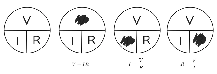
Many electricians use the Ohm’s Law circle to remember the formula. Voltage is at the top, current on the left, and resistance on the right. Cover the one you want to find, and the circle shows you how to calculate it. For example, cover voltage and you see that voltage equals current times resistance.
In my experience, Ohm’s Law isn’t just a formula—it’s a way to understand how electricity works. Whether you’re sizing wires or fixing a problem, it’s your best tool for figuring out what’s going on in a circuit.
Power Fomula
Power is all about how much work your electrical system can do—and more importantly, how much energy it uses. So how do you figure it out?
The basic formula is:
P = V \times Iwhere P is power (in watts), V is voltage (in volts), and I is current (in amps). There are other versions too, depending on what you know:
P = I^2 \times R P = \frac{V^2}{R}These help you understand how much power a device uses and whether your wiring and circuit can handle it.
Practical Applications
Let’s say you’re installing a new refrigerator that runs at 120V and 10A.
P = V \times I = 120 \times 10 = 1,200WThat tells you how much power it needs, so you can make sure your circuit won’t overload.
But what if you don’t know the current? If you know resistance instead, use P = \frac{V^2}{R}
For example, a heater with 10Ω on a 240V supply consumes:
P = \frac{V^2}{R} = \frac{240^2}{10} = \frac{57,600}{10} = 5,760WThat’s helpful for sizing breakers or wires.
Or maybe you know current and resistance but not voltage. Then use P = I^2 \times R
For instance, if a motor draws 5A through a 2Ω resistor:
P = I^2 \times R = (5)^2 \times 2 = 50WThis is great for calculating heat loss or checking if a component can handle the load without failing.
Real-World Example
In real-world applications, power calculations are everywhere. I remember a project where we needed to size a generator for construction tools.
We added up all the power ratings: a table saw (3,000W), a compressor (1,500W), and lights (200W). Total: 4,700W. That told us we needed a generator with at least that capacity to avoid shutdowns or overloads.
Power Factor Considerations
Power factor (PF) also matters, especially in three-phase systems. It’s the ratio of real power to apparent power. The formula is:
P = \sqrt{3} \times V \times I \times \text{PF}A low PF means you need more current for the same real power, which can lead to larger wires and higher costs.
| Formula | Use When You Know | What It’s Good For |
|---|---|---|
| P = V × I | Voltage, Current | Basic power calculation |
| P = I² × R | Current, Resistance | Calculate heat loss or resistor power use |
| P = V² ÷ R | Voltage, Resistance | Power drawn by a fixed load |
Easy Way to Remember
To remember this easily, I use the english word “PIE” to recall that Power (P) equals Voltage (V) times Current (I). It’s simple and easy to remember. Also, knowing that 1 watt equals 1 volt times 1 ampere makes the idea stick in your mind.
In summary, calculating power ensures your systems are efficient and safe. Whether you’re sizing circuits or choosing equipment, these formulas are your best friends.
Voltage Drop
Have you ever noticed your lights dim when you turn on a high-power appliance? That’s voltage drop at work. Let’s learn how to calculate and manage it.
Voltage drop happens when voltage decreases along a wire because the wire resists the flow of electricity. For simple cases, use:
V_{\text{drop}} = I \times RWhere Vdrop is voltage drop, I is current, and R is resistance. For more detailed calculations in single-phase systems, use:
V_{\text{drop}} = \frac{K \times Q \times I \times D}{CM}Here, K is a constant for the wire material, Q is power factor(2 for single-phase, √3 for three-phase), D is distance (one-way), and CM is the wire’s cross-sectional area in circular mils.
Keeping voltage drop low is important so your devices get enough voltage to work properly.
Why Voltage Drop Matters
Voltage drop is a sneaky problem in electrical work. If it’s too high, lights dim, motors difficult to start, or sensitive electronics malfunction. That’s why calculating it is so important.
Let’s say you’re wiring a house with a 120V circuit running 100 feet from the panel to an outlet. You’re using 14 AWG copper wire, which has a resistance of about 2.525Ω per 1000 feet. With a 15A breaker, current is 15A.
Since electricity travels to the outlet and back, the total wire length is 200 feet. So total resistance is:
R_{\text{total}} = \frac{2520}{1000} \times 200 = 0.505 \OmegaVoltage drop is:
V_{\text{drop}} = I \times R = 15 \times 0.505 = 7.575VThat means the outlet gets:
120 - 7.575 = 112.425VThat’s about a 6.3% drop, which is too high. The National Electrical Code (NEC) recommends no more than 3%. To fix this, you’d need to use thicker wire, like 12 AWG, which has less resistance.
Advanced Calculations
For longer runs or AC circuits, use:
V_{\text{drop}} = \frac{2 \times K \times I \times D}{CM}(K is 12.9 for copper, 21.2 for aluminum).
For example, a 20A circuit on 12 AWG copper (CM = 6,530) over 50 feet:
V_{\text{drop}} = \frac{2 \times 12.9 \times 20 \times 50}{6,530} \approx 3.95 Vor 3.3% of 120 volts—just inside the limit.
For three-phase systems, the formula is:
V_{\text{drop}} = \frac{1.732 \times K \times I \times D}{CM}How to Fix Voltage Drop?
To reduce voltage drop, use thicker wires or shorten distances. On one job installing parking lot lights far from the panel, we initially used standard wire size—but the lights were dim. After calculating voltage drop (it was too high), we upgraded to larger wire and fixed it.
| Wire Size (AWG) | Circular Mil Area (CM) | Copper Resistance (Ω/1,000 ft) | Aluminum Resistance (Ω/1,000 ft) |
|---|---|---|---|
| 14 | 4,110 | 2.525 | 4.04 |
| 12 | 6,530 | 1.588 | 2.53 |
| 10 | 10,380 | 0.999 | 1.62 |
| 8 | 16,510 | 0.628 | 1.02 |
| 6 | 26,240 | 0.395 | 0.65 |
In short, understanding voltage drop ensures your systems perform well and meet code requirements. It’s all about choosing the right wire size for the job.
Conductor Fill Formula
Stuffing too many wires into a conduit is like overpacking a suitcase—it’s a mess and can cause trouble. Proper sizing keeps everything safe and meets electrical codes. Let’s see how it’s done.
Conduit and conductor sizes are calculated using the conductor fill formula:
CF = \frac{A \times N}{T}where CF is fill percentage, A is conductor area, N is number of conductors, and T is conduit area. The NEC limits how full conduits can be: 53% for one conductor, 31% for two, and 40% for three or more.
Conductor Fill Basics
Overfilling conduits can cause wires to overheat, damage their insulation, or make pulling wires harder. That’s why the NEC sets these limits.
For example, a 1-inch conduit has about 0.785 square inches of space. If you use three 12 AWG wires (each taking up 0.0133 square inches), the fill is:
CF = \frac{0.0133 \times 3}{0.785} \times 100\% = 5.08 \%well under the 40% limit for three conductors. But if you add more wires, you’ll need to check the fill again.
Conduit Bending Precision
Bending conduit correctly is important too. For an offset bend, multiply the offset distance by a factor based on the bend angle. For example, a 30° bend uses a multiplier of 2.0. So, a 6-inch offset needs 12 inches of straight conduit between bends.
For rolling offsets, use the Pythagorean theorem ($$ c^2 = a^2 + b^2 $$) to find the diagonal distance. I once saw an apprentice struggle with this until the electrician drew it out and used the formula—it made sense then, and the conduit fit perfectly.
Real-World Challenges
On a commercial job, we had to run multiple circuits through a single conduit. Miscalculating the fill led to overheating, tripping breakers. Recalculating with the NEC limits and upgrading the conduit size solved it. Bending also matters—sloppy bends can pinch wires or misalign runs, wasting time.
| Calculation Type | Formula/Rule | Key Considerations |
|---|---|---|
| Conductor Fill | CF = (A × N) ÷ T | NEC limits: 53% (1), 31% (2), 40% (3+) |
| Offset Bend | Multiplier (e.g., 30° = 2.0) | Distance = offset × multiplier |
| Rolling Offset | c² = a² + b² | Calculate diagonal length |
These calculations keep your installations safe and efficient, meeting NEC standards.
Conclusion
Knowing these simple electrical formulas and rules makes a big difference when working on any electrical project. They help you design safe circuits, fix problems faster, and avoid mistakes that could cause damage or danger. Whether you’re just starting out or have been working in the field for years, understanding these basics will help you work smarter and safer.