Electricity flows through our buildings every second of the day, and in the background, MCCBs quietly keep everything safe. They are easy to overlook—just another device in a cabinet—yet their job is far more complex than the simple switch they resemble.
Problems often begin when the MCCB isn’t matched to the system as well as it should be. A machine might trip during startup, cables may run hotter than expected, or a panel may need frequent resets. These small annoyances often make maintenance teams trouble, but the root cause is commonly an MCCB that wasn’t selected with the whole system in mind.
Even experienced engineers can overlook subtle factors during specification. These details rarely cause immediate trouble, but they often influence how stable, efficient, and predictable a system will be over time. A thoughtful selection approach helps keep everything operating as intended.
Undersizing the MCCB Current Rating
Undersizing MCCBs is more common than you might expect. This usually happens because calculations are rushed or safety margins are overlooked, leading to choices that seem logical on paper but cause problems in practice.
Take an 80A load as an example. An engineer might be tempted to select an 80A MCCB. However, for continuous loads—those running more than three hours—you must apply a 125% safety factor. That means the same 80A load actually requires at least a 100A MCCB. Skipping this step often results in nuisance trips and accelerates wear on the breaker.
So why 125%? MCCBs rely on thermal-magnetic components that naturally heat up under continuous operation. The bimetallic strip inside bends when exposed to prolonged heat, which over time speeds up internal wear. In many plants, 63A MCCBs are used on circuits carrying 60A continuous loads. Even without any faults or overloads, these breakers can trip repeatedly simply because they are operating near their rated capacity. The heat buildup creates thermal stress that triggers mis-trips.
The consequences go beyond occasional downtime. Operating an undersized MCCB under constant thermal stress shortens its lifespan. A properly sized breaker can last 20–25 years, whereas an undersized one may need replacement in just 5–7 years. Any upfront savings are quickly outweighed by the cost of maintenance and early replacement.
The correct approach is straightforward: multiply the continuous load by 1.25, then select the next standard MCCB size. For circuits with motors, also account for inrush currents. Finally, always document your calculations. Doing so ensures that future engineers understand your reasoning and avoid repeating the same mistake.
Ignoring Breaking Capacity & Fault Current
Ignoring breaking capacity is one of the most dangerous mistakes in electrical design. Every point in a system has a prospective short-circuit current (PSCC)—the maximum current that could flow if a fault occurs. This value depends on the transformer size, cable impedance, and distance from the source. The closer you are to the transformer, the higher the fault current.
MCCBs have two key ratings: ultimate breaking capacity (Icu) and service breaking capacity (Ics). Ics is typically only 25–75% of Icu. Exceeding these limits can lead to catastrophic failures: the breaker case can rupture, contacts can weld together, or the breaker can explode, causing arc flashes, severe burns, equipment damage, and even fires. (Related Reading: Icu and Ics on Circuit Breakers: What You Need to Know)
To prevent such dangers, you should always calculate your system’s PSCC by considering the transformer rating, cable length and size, and distance to the breaker. Then select an MCCB with an Icu equal to or higher than this value. This is why Sincede’s MCCBs are engineered with reinforced arc chutes and rigorously tested to ensure the actual breaking capacity meets the labeled specifications.
For critical systems like hospitals or data centers, it’s wise to choose breakers where Ics equals 100% of Icu. Never assume a breaker is “good enough” without proper verification—fault currents often exceed expectations, and the consequences can be deadly.
Selecting the Wrong Trip Curve Type
Trip curves determine how quickly an MCCB reacts to overcurrent, and choosing the wrong type can lead to frequent nuisance trips or inadequate protection.
Each trip curve has a magnetic trip threshold: Type B (3–5× rated), Type C (5–10×), and Type D (10–20×). While the thermal trip is similar across all types, the magnetic threshold influences real-world performance. For instance, a motor drawing six times its rated current would instantly trip a Type B breaker but not a Type C.
Practical guidance: Type B is suitable for resistive loads such as lighting or heaters. Type C works well for small motors, HVAC equipment, and most mixed commercial loads, making it the safest choice in many cases. Type D is necessary for highly inductive loads like large motors or transformers. Less common curves, such as Type K for frequent motor cycling and Type Z for sensitive electronics, address specific needs.
The most frequent mistake is selecting breakers based on availability or cost rather than load requirements. While the price difference between curve types is minimal, using the wrong type can considerably increase maintenance, downtime, and operational costs.
Failing to Coordinate Protection Devices for Selectivity
Selectivity—or coordination—ensures that when a fault occurs, only the breaker closest to the problem trips, leaving the rest of the system working as usual. Without proper coordination, even a small branch fault can shut down the entire system, leading to extended downtime and tremendous production losses.
Coordination isn’t just about convenience—it’s essential for safety and system reliability. The NEC requires it for emergency systems, life safety circuits, and healthcare facilities. Even in standard commercial or industrial buildings, poor coordination can make troubleshooting harder and can damage equipment when power is suddenly lost.
There are several approaches to achieve coordination:
-
Current selectivity: Set the upstream breaker’s threshold higher than downstream breakers. Simple, but limited by fault current range.
-
Time selectivity: Introduces intentional delays for upstream breakers, allowing downstream devices to clear faults first.
-
Energy selectivity: Limits peak fault current to prevent upstream breakers from tripping unnecessarily.
-
Zone selective interlocking (ZSI): Uses electronic communication between breakers to ensure the closest breaker acts first, ideal for critical systems.
A proper coordination study looks at how all the breakers respond to different levels of fault current. Skipping this step is risky. Always use manufacturer tables, specialized software, or hire a professional engineer. The time and cost to do it right are small compared to the problems and safety risks caused by poor coordination.
Not Accounting for Environmental & Temperature Derating
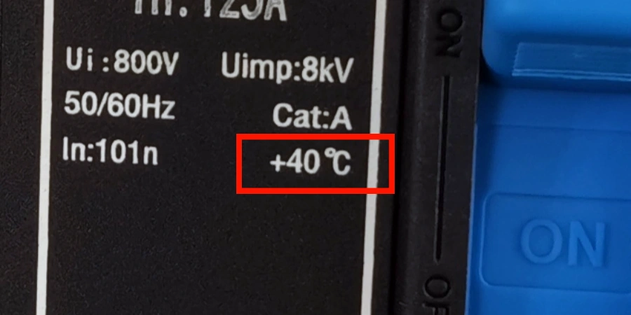
Temperature derating is often overlooked, but it can significantly reduce a breaker’s capacity. MCCBs are rated for 40°C ambient, yet higher temperatures can lower their effective current. For example, a 100A breaker in a 60°C enclosure may only handle 90–95A, causing nuisance trips even when the load seems correct.
Thermal-magnetic breakers rely on a bimetallic strip that bends with heat. When the ambient temperature is higher, the strip starts warmer, so it trips at a lower current. Most manufacturers provide derating curves—typically 4–5% per 10°C above 40°C. Cold environments can also create problems, making components brittle or slower to react.
Other environmental factors further affect performance. High altitude reduces cooling and arc performance (derate 3–5% per 1,000m above 2,000m). High humidity can cause condensation and corrosion, while dust and debris reduce cooling and interfere with mechanical operation. Vibration and corrosive atmospheres can damage contacts. Proper enclosures, IP ratings, or corrosion-resistant breakers help reduce these risks.
Proximity is another hidden factor. When multiple breakers are installed side-by-side, they heat each other, raising the effective ambient temperature. Manufacturers often recommend adding 5–10% derating for crowded panels.
Example: For a 95A continuous load, first apply the 125% factor:
95×1.25=118.75A95 \times 1.25 = 118.75\text{A}95×1.25=118.75ANext, apply temperature derating (7.5% → multiply by 0.925) and proximity derating (5% → multiply by 0.95):
125×0.925×0.95=109.84A125 \times 0.925 \times 0.95 = 109.84\text{A}125×0.925×0.95=109.84ASince 109.84A < 118.75A, the 125A breaker is insufficient. Choose the next standard size: 150A.
Always document your derating calculations. This not only explains your design choices but also prevents future engineers from “optimizing” the system in ways that could cause frequent trips or premature breaker failures.
Incorrect Wire Sizing and Connection Methods
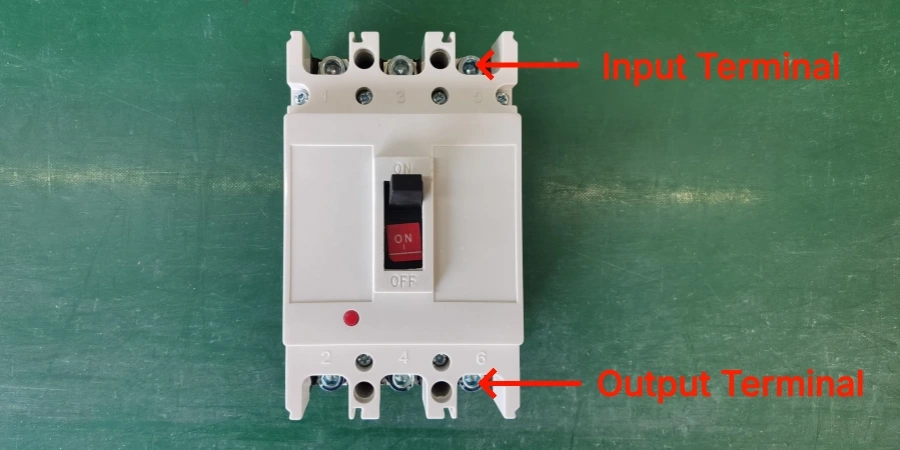
Conductor size and wiring methods may seem like installation issues, but they directly affect MCCB selection. The breaker’s terminals must be able to accept the conductor size required for the load. Many projects choose the correct MCCB electrically, only to discover during installation that the terminals cannot accommodate the necessary cable. Undersized conductors lead to loose connections and overheating, while oversized conductors create mechanical stress and poor contact—both unsafe.
Terminal compatibility varies with MCCB frame size. Smaller breakers often allow direct wire termination, while larger ones require crimped or mechanical lugs. Selecting an MCCB without checking terminal requirements often forces installers to use improvised connectors, creating long-term reliability risks. Proper torque is equally important: insufficient torque causes heating, and excessive torque damages terminals or conductors.
Physical space for cable bending is another often-overlooked issue. Large cables—such as 250 MCM and above—require significant bend radius. In many compact panelboards, conductors simply cannot be routed into the MCCB without excessive force, leading to insulation stress or the need to redesign the layout.
Best practice includes selecting conductors based on load calculations, using the correct type of lugs, applying manufacturer-specified torque with a calibrated wrench, and performing a pull test after tightening. MCCB selection should therefore consider the entire wiring path: load current, conductor size, terminal capacity, connection method, and available space. Ignoring any of these factors increases the risk of failures, rework, and unsafe installations.
Overlooking Standards Compliance
Standards compliance may not be exciting, but it’s essential for safety, legality, and reliability. In North America, the NEC governs MCCBs, while internationally IEC 60947-2 applies. Both ensure breakers are properly rated, coordinated, and tested, so skipping compliance can cause serious problems.
NEC rules cover more than just current ratings. For example, continuous loads must follow the 125% rule, and breakers must have an interrupting rating higher than the available fault current. Additionally, selective coordination is required for emergency, standby, and healthcare systems. Failing to follow these requirements can lead to code violations and operational failures.
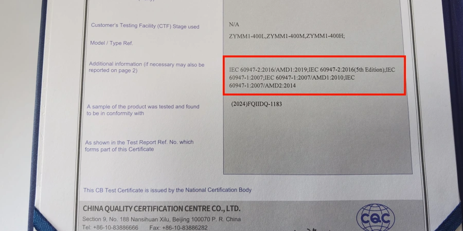
Similarly, IEC 60947-2 sets standards for breaker categories, interrupting ratings (Icu/Ics), and testing procedures. Understanding these ensures you select the right breaker for your application, especially in international projects where standards differ.
Documentation and verification tie everything together. Keep records of load calculations, derating factors, fault currents, and coordination studies. After installation, test and confirm breaker settings, terminal torque, and correct installation. This ensures your system not only meets code but will operate reliably.
Ignoring standards carries multiple risks: legal consequences, equipment failure, nuisance trips, and project delays. At Sincede, we take compliance seriously. As a source factory with ISO, CB, and CE certifications, we ensure every breaker leaving our factory meets strict IEC 60947-2 standards. By following these rules from the start, you save money, prevent downtime, and keep your electrical system safe and reliable.
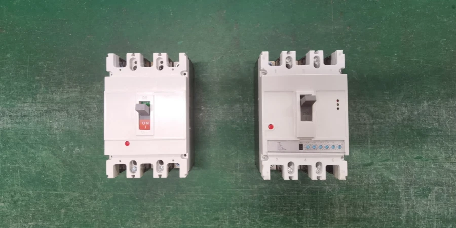
Trip Unit Selection Errors: Thermal vs Electronic
Choosing between thermal-magnetic and electronic trip units is a key MCCB decision, yet many people base it only on price. Thermal-magnetic units use a bimetallic strip for overload protection and a magnetic coil for short-circuit trips. They are simple, reliable, and handle motor start-ups well. However, their trip current is affected by ambient temperature, which can lead to nuisance trips in hot environments.
Electronic trip units work differently. They use microprocessors to monitor current, compensate for temperature, and allow adjustable settings. Many models also offer ground fault protection, diagnostics, and communication with building or SCADA systems. This makes them ideal for sensitive equipment or critical systems, ensuring consistent protection even under changing environmental conditions.
So, when should you choose each type? Thermal-magnetic units are best for simple, cost-sensitive circuits or standard motor loads with high inrush currents. Electronic units are worth the extra cost when precision, adjustability, temperature compensation, or monitoring is important—such as in data centers, critical manufacturing, or temperature-sensitive installations. (Thermal-Magnetic vs Electronic MCCB, Which One Do You Need?)
The key takeaway: match the trip unit to the load and conditions, not just the price. Picking the wrong type can cause nuisance trips, damage equipment, or lead to costly replacements.
Not Planning for Future System Expansion
When selecting MCCBs, it’s easy to focus only on today’s load. But electrical demands almost always grow over time—new equipment, extra lighting, expanded HVAC, or additional circuits. If you size breakers and panels just for current needs, any future growth can mean expensive retrofits, new panels, and disruption.
A common mistake is installing a distribution panel with exactly enough breaker slots for current circuits. When loads increase, you may need a second panel, new feeders, or even larger breakers—costing far more than simply planning for spare capacity upfront.
Best practice: plan for 25–30% extra capacity. For example, if the calculated load is 400A, select a main breaker and busbars rated for 500–550A. If you need 16 circuits, use a panel with 20–24 slots. Spare capacity should extend to all parts of the system—main breaker, feeders, and panel space.
Facility type matters: manufacturing may need one or two extra large loads; offices grow gradually; warehouses and data centers can expand rapidly. Understanding your client’s growth helps size the system correctly.
Flexible frame selection also helps. Choose MCCB frames that allow uprating by changing the trip unit, without replacing the breaker. A 250A frame can fit a 130A trip unit today and be upgraded to 200–250A later—saving cost and downtime.
Finally, document your planning. Record current loads, planned spare capacity, breaker frame sizes, and future assumptions. Clear documentation ensures future modifications are safe and efficient.
The key principle: electrical infrastructure lasts decades, but loads change faster. Planning for growth with modest upfront investment can avoid expensive upgrades, keep systems reliable, and gives your facility flexibility for the future.
Selecting Based Only on Price
A lot of people still say, “All MCCBs are the same—just buy the cheapest one.” This idea sounds simple, but it causes huge problems later. Two breakers can look identical on paper but perform very differently in real life. If you only look at the price tag, you will almost always pay more in the long run.
Here’s how it usually happens. A project goes out for bid, and one supplier offers breakers that are much cheaper than the others. The contractor wants a low bid, the owner wants to save money, and the cheap option gets approved. At first, everything seems fine. But after a year or two, the problems start. Breakers trip for no reason, fail to trip when they should, run hot, or simply wear out too fast. Replacement parts are hard to get, and technical support is slow or nonexistent. Soon the facility is spending more time and money on repairs than they ever saved during installation.
The root cause is quality. Good MCCBs use better metals for the contacts, stronger materials in the case, and well-designed arc chutes. They also go through strict testing and quality control. Low-quality breakers often skip these steps, which leads to unreliable performance and shorter life.
These quality differences matter because they create hidden costs—extra downtime, frequent replacements, and longer repair times. A well-made breaker can last decades. A cheap one might last only a few years.
So when choosing MCCBs, price should not be the only factor. However, reliable quality doesn’t always require an inflated budget. The smartest sourcing strategy is to work directly with a manufacturer who controls quality at the source.
With 26 years of experience, Sincede controls the entire production chain—from internal mold making to final assembly. This allows us to deliver Tier-1 quality breakers without the distributor markup, ensuring you don’t have to choose between cost and performance.
In the end, choosing better equipment protects both your facility and your professional reputation.
Conclusion
MCCB selection may seem routine, but it’s a subtle art of balancing safety, cost, and flexibility. Thinking like a system designer—anticipating faults, growth, and environmental stresses—turns an ordinary circuit into one that quietly works, reliably, for decades.
If you are looking for a manufacturing partner who prioritizes these critical details as much as you do, we invite you to explore Sincede’s complete range of low-voltage circuit protection solutions. We are always ready to support your supply chain with the consistency and safety your projects demand.